
Understanding the fundamental distinctions between parallel and series circuits is crucial for anyone delving into electronics, electrical engineering, or even just basic home improvement. These two configurations dictate how electrical components are connected and, consequently, how current flows, voltage is distributed, and resistance impacts the overall system. While both aim to deliver electricity, their operational principles and practical applications diverge significantly, offering unique advantages and disadvantages that shape modern technology.
The Foundational Principles of Electrical Circuits
At its core, an electrical circuit is a closed loop through which electrons can flow, driven by a voltage source (like a battery or power outlet) and encountering resistance from components (such as light bulbs, resistors, or motors). For current to flow, the circuit must be complete, forming an unbroken path from the positive terminal of the voltage source, through the components, and back to the negative terminal. The behavior of electricity within this loop is governed by Ohm’s Law (V=IR), which relates voltage (V), current (I), and resistance (R), and Kirchhoff’s Laws, which describe how current and voltage behave at junctions and loops within a circuit.
Components of a Basic Circuit
Every functional circuit, regardless of its configuration, comprises several key elements:
-
Voltage Source: Provides the electrical potential difference (e.g., battery, generator).
-
Conductors: Materials that allow electrons to flow easily (e.g., wires).
-
Load/Components: Devices that consume or utilize electrical energy, offering resistance to current flow (e.g., resistors, LEDs, motors).
-
Switch (Optional but common): A device used to open or close the circuit, controlling the flow of electricity.
The way these loads or components are arranged – either one after another or side-by-side – determines whether the circuit is series or parallel, with profound implications for its functionality and reliability.
Series Circuits: A Single Path for Current
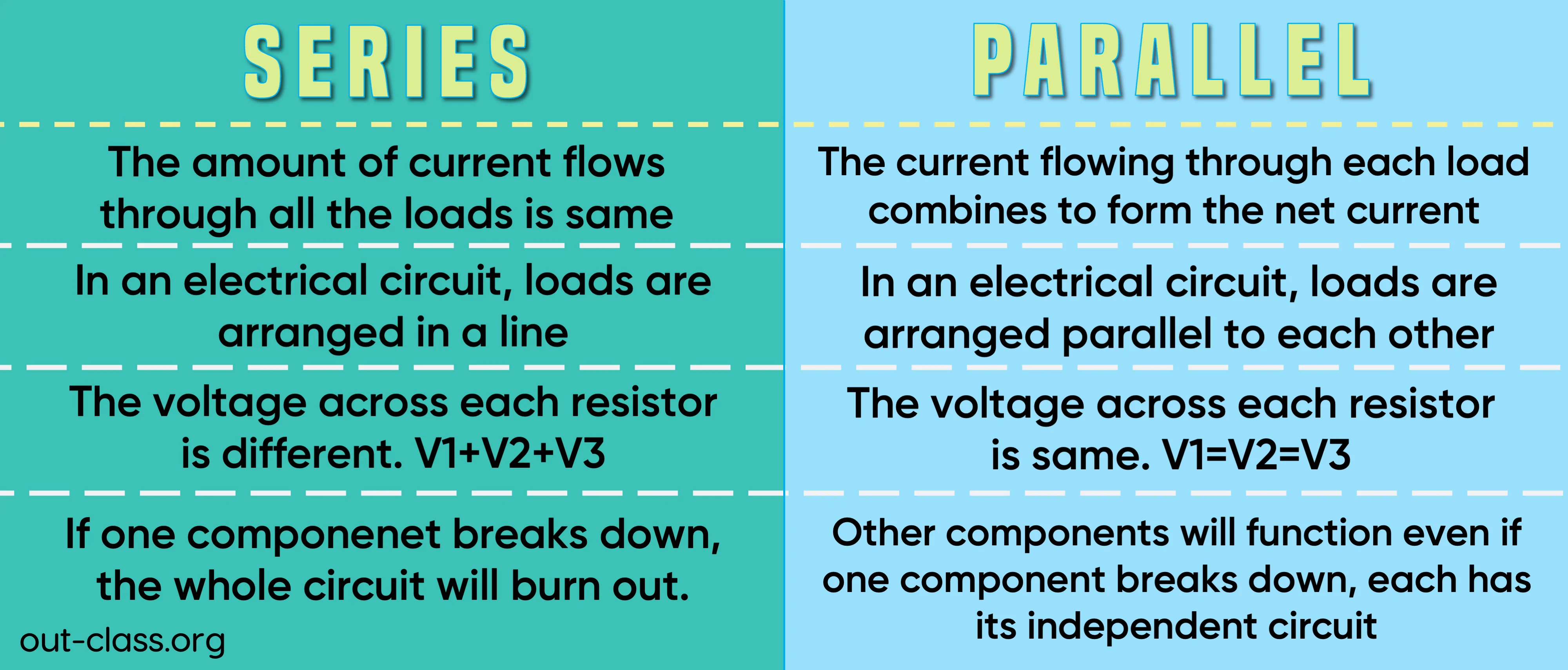
Imagine a single lane road where all cars must pass through the same checkpoints one after another. This analogy perfectly describes a series circuit. In a series configuration, components are connected end-to-end, forming a single, continuous loop. There is only one path for the current to take from the voltage source, through each component, and back to the source.
Characteristics of Series Circuits
The unique arrangement of series circuits results in several defining characteristics:
Current is Constant
In a series circuit, the current flowing through every component is the same. There’s nowhere else for the electrons to go; if 1 amp leaves the voltage source, 1 amp must pass through the first resistor, the second resistor, and so on, before returning to the source. This is a direct consequence of the single-path nature.
Voltage Divides Across Components
While the current remains constant, the total voltage supplied by the source is divided among the components in the circuit. Each component “drops” a portion of the total voltage, proportional to its resistance. The sum of the voltage drops across all components equals the total voltage supplied by the source. For example, if a 12V battery powers two identical light bulbs in series, each bulb will have 6V across it.
Total Resistance Adds Up
The total resistance of a series circuit is simply the sum of the individual resistances of all components. If you have resistors R1, R2, and R3 in series, the total equivalent resistance (R_total) is R1 + R2 + R3. This means that adding more components in series will always increase the total resistance of the circuit, which in turn (by Ohm’s Law, I=V/R) decreases the total current flowing through it.
Disadvantages of Series Wiring
The single-path nature of series circuits leads to significant drawbacks:
-
Single Point of Failure: If any single component in a series circuit fails (e.g., a light bulb burns out, creating an open circuit), the entire circuit is broken, and current stops flowing to all other components. This is why old strings of Christmas lights would go completely dark if one bulb failed.
-
Reduced Brightness/Performance: As more components are added in series, the total resistance increases, and the current decreases. If the components are identical (like light bulbs), the voltage drop across each decreases, leading to dimmer lights or reduced performance.
-
Cannot Control Components Independently: You cannot switch on or off individual components in a series circuit without affecting the others.
Parallel Circuits: Multiple Paths for Power
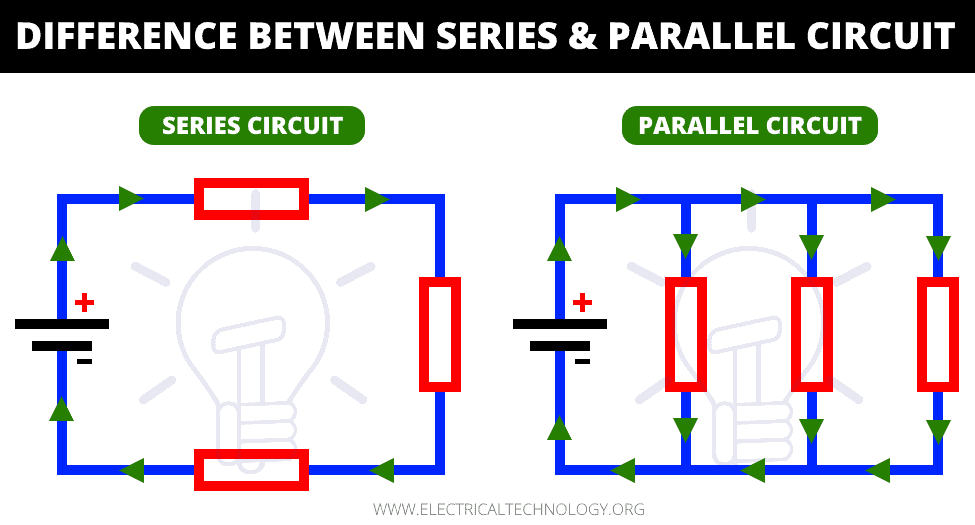
In contrast to the single-lane road of a series circuit, a parallel circuit resembles a multi-lane highway or a river splitting into several streams. In a parallel configuration, components are connected across the same two points in the circuit, creating multiple, separate paths for the current to flow. Each component essentially has its own independent branch connected directly to the voltage source.
Characteristics of Parallel Circuits
The multi-path design of parallel circuits gives them distinct operational characteristics:
Voltage is Constant Across Components
A defining feature of parallel circuits is that the voltage across each parallel branch, and thus across each component within that branch, is the same and equal to the total voltage supplied by the source. Because each branch connects directly to the same two points (the terminals of the voltage source), they all experience the full potential difference. For instance, in household wiring, all outlets and light fixtures are connected in parallel, ensuring that each receives the full 120V supply.
Current Divides Among Branches
Unlike series circuits, the total current supplied by the source in a parallel circuit splits among the different branches. The amount of current flowing through each branch is inversely proportional to its resistance (I = V/R). Branches with lower resistance will draw more current, while branches with higher resistance will draw less. The sum of the currents in all individual branches equals the total current drawn from the voltage source.
Total Resistance Decreases with More Components
When components are added in parallel, the total resistance of the circuit actually decreases. This is because adding more paths provides more opportunities for current to flow, effectively reducing the overall opposition to current. The formula for total resistance in parallel is R_total = 1 / (1/R1 + 1/R2 + 1/R3 + …). For identical resistors, adding more in parallel decreases the overall resistance, leading to a higher total current draw from the source.
Advantages of Parallel Wiring
The multiple-path structure offers significant benefits:
-
Independent Operation: Each component in a parallel circuit operates independently. If one component fails (becomes an open circuit), the current can still flow through the other branches, allowing them to continue functioning. This is why if one light bulb in a modern Christmas light string burns out, the rest remain lit.
-
Consistent Performance: Since each component receives the full source voltage, its performance (e.g., brightness of a bulb, speed of a motor) remains consistent regardless of how many other components are connected in parallel, as long as the power source can supply enough total current.
-
Allows Independent Control: Each branch can have its own switch, enabling individual components to be turned on or off without affecting others.
Key Differences in Operation and Application
The contrasting characteristics of series and parallel circuits lead to vastly different operational behaviors and practical applications in technology and everyday life.
Impact of Component Failure
-
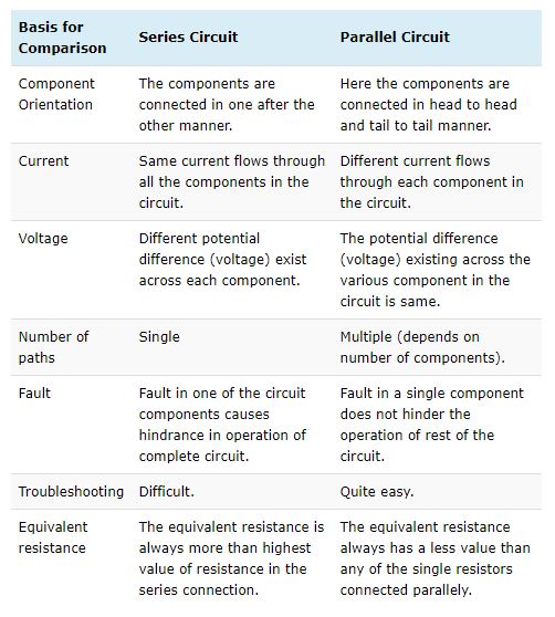
Series: A single component failure causes the entire circuit to break and all other components to cease functioning. This makes series circuits less reliable for applications where continuous operation is critical.
-
Parallel: A single component failure (as an open circuit) generally only affects that specific branch, allowing other components to continue operating. This offers greater reliability and redundancy.
Voltage and Current Characteristics
-
Series: Constant current, divided voltage. Adding more components increases total resistance and decreases total current.
-
Parallel: Constant voltage, divided current. Adding more components decreases total resistance and increases total current.
Total Resistance Behavior
-
Series: Total resistance is the sum of individual resistances (R_total = R1 + R2 + …).
-
Parallel: Total resistance is less than the smallest individual resistance (1/R_total = 1/R1 + 1/R2 + …).
Practical Applications and Why It Matters
Understanding these differences is not just theoretical; it underpins the design of almost every electrical and electronic system we interact with.
Household and Industrial Wiring
All residential and commercial electrical systems are wired in parallel. This ensures that every appliance, light fixture, and outlet receives the full 120V (or 230V in many regions) from the main power supply, allowing them to operate at their intended voltage. If homes were wired in series, turning off one light switch would plunge the entire house into darkness, and adding more appliances would dim existing lights.
Electronic Devices and Battery Packs
Modern electronic devices often incorporate a combination of series and parallel elements. For instance, within a complex circuit board, certain sub-circuits might be in series (e.g., for voltage division to power different parts of a chip), while others are in parallel (e.g., to power multiple LEDs or functional blocks). Battery packs are a prime example: connecting batteries in series increases the total voltage (e.g., four 1.5V AA batteries in series yield 6V), while connecting them in parallel increases the total current capacity (amperage-hours) while keeping the voltage the same.
Lighting Systems
Old Christmas tree lights were famously wired in series; when one bulb burned out, the entire string went dark, necessitating a tedious search for the faulty bulb. Modern Christmas lights, however, typically use parallel wiring for sections or individual bulbs, so a single failure doesn’t affect the rest of the string. Car headlights and taillights are also wired in parallel for reliability.
In conclusion, the choice between a series and a parallel circuit configuration is fundamental to electrical design, driven by the specific requirements for voltage, current, power distribution, and reliability. Series circuits are simpler to construct for certain purposes and can be useful for voltage division or current limiting, but their single point of failure and voltage division across components limit their widespread application in complex systems. Parallel circuits, with their independent component operation, consistent voltage distribution, and inherent redundancy, are the backbone of most electrical infrastructure and electronic devices, ensuring reliability and flexibility in our technologically advanced world.
aViewFromTheCave is a participant in the Amazon Services LLC Associates Program, an affiliate advertising program designed to provide a means for sites to earn advertising fees by advertising and linking to Amazon.com. Amazon, the Amazon logo, AmazonSupply, and the AmazonSupply logo are trademarks of Amazon.com, Inc. or its affiliates. As an Amazon Associate we earn affiliate commissions from qualifying purchases.