In the realm of consumer electronics and high-fidelity audio, the power amplifier stands as a pivotal piece of hardware. Whether you are upgrading a sophisticated home theater system or enhancing a vehicle’s mobile media hub, the installation of an amplifier (amp) represents a significant leap in audio performance. This technical guide explores the nuances of amplifier integration, providing a professional roadmap for those looking to master the hardware side of audio technology. By understanding the signal chain, power requirements, and thermal dynamics, tech enthusiasts can transform a mediocre soundstage into a studio-grade experience.
Understanding the Core Components and Technical Preparation
Before turning a single screw, it is imperative to understand the technology behind the amplification process. An amplifier’s primary function is to take a low-level audio signal from a source unit—such as a digital-to-analog converter (DAC), a head unit, or a smartphone—and increase its amplitude to a level sufficient to drive loudspeakers. This requires a robust understanding of electrical circuits and signal integrity.
Choosing the Right Amplifier for Your Setup
The first step in any tech installation is hardware selection. Amplifiers are generally classified by their circuitry architecture, most commonly Class AB or Class D. For modern tech integrations, Class D amplifiers are increasingly popular due to their high efficiency and compact footprint, utilizing pulse-width modulation (PWM) to switch transistors on and off rapidly.
When selecting your hardware, you must match the amplifier’s RMS (Root Mean Square) power output with the power handling capabilities of your speakers. Furthermore, impedance matching is critical; running a 2-ohm load on an amplifier rated only for 4 ohms can lead to thermal runaway and hardware failure. Always consult the technical specification sheet of your hardware to ensure a synergistic match between the source, the amp, and the transducers.
Essential Tools and Technical Equipment
Installing an amplifier is a precision task that requires a specific toolkit. Beyond standard screwdrivers and sockets, you will need a digital multimeter to test voltage and continuity. For the wiring, high-quality oxygen-free copper (OFC) cables are recommended over copper-clad aluminum (CCA) to ensure maximum current flow and minimal resistance.
You will also need:
- Wire strippers and high-grade crimping tools.
- Heat shrink tubing for professional-grade insulation.
- A power distribution block and an in-line fuse holder (essential for circuit protection).
- Cable ties and grommets for secure wire management.
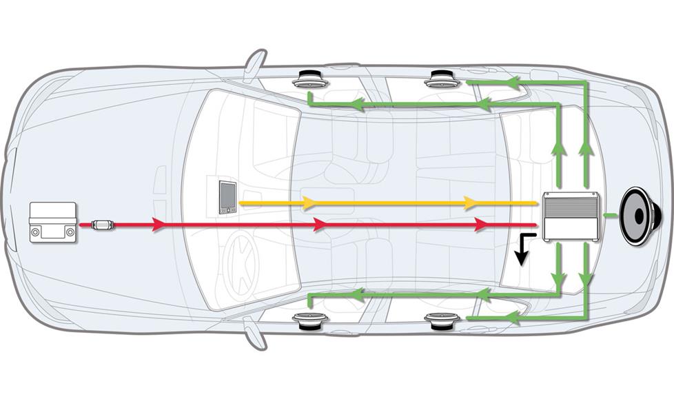
Planning the Signal Path and Power Grid
A successful tech installation relies on meticulous planning. You must determine the optimal mounting location—somewhere with adequate airflow to prevent thermal throttling. In a vehicle, this is often under a seat or in the trunk; in a home, it is usually within a ventilated media rack.
Equally important is the “signal-to-noise” hygiene. You must plan to route your high-voltage power cables on the opposite side of the enclosure or vehicle from your low-level RCA signal cables. This physical separation prevents electromagnetic interference (EMI) and “alternator whine” or 60Hz hum from polluting the audio signal.
The Step-by-Step Installation Process
Once the planning phase is complete, the physical installation begins. This process requires a methodical approach to ensure both the safety of the installer and the longevity of the hardware.
Establishing the Power Foundation
The most critical aspect of amplifier installation is the power circuit. You must connect the main power wire directly to the positive terminal of the power source (typically the battery). However, the “golden rule” of audio tech installation is to always disconnect the negative battery terminal before starting to prevent accidental short circuits that could fry the vehicle’s ECU or the home’s sensitive electronic components.
Install an in-line fuse within 12 to 18 inches of the power source. This fuse acts as a fail-safe; if the power cable is ever pinched or grounded, the fuse will blow, protecting the rest of your tech stack from a catastrophic electrical fire.
Mounting the Hardware Securely
The physical placement of the amplifier is not just about aesthetics; it is about mechanical stability and thermal management. Use mounting screws to secure the amplifier to a non-conductive surface. If you are mounting to a metal chassis, consider using a wooden or plastic mounting board to provide an extra layer of isolation. This reduces the risk of creating a “ground loop,” a common tech issue where multiple paths to ground cause unwanted interference in the audio output. Ensure the cooling fins of the amplifier are unobstructed to allow for passive or active heat dissipation during high-output sessions.
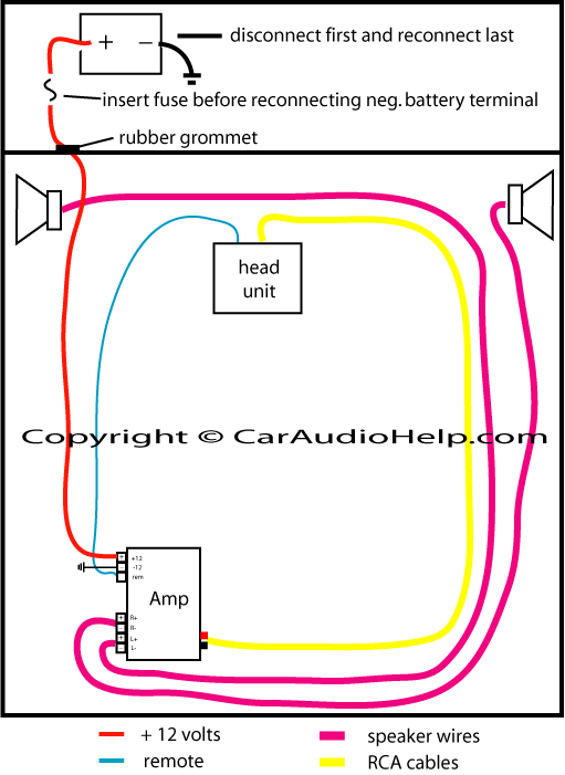
Grounding and Remote Turn-On
An amplifier is only as good as its ground connection. The ground wire should be as short as possible and attached to a solid, bare-metal point on the chassis (or the dedicated ground bus in a home rack). Remove any paint or rust at the contact point to ensure a low-resistance connection.
Finally, connect the “Remote Turn-On” (REM) wire. This is a low-voltage trigger (usually 12V) that tells the amplifier to wake up when the source unit is powered on. Without this, the amplifier would either stay on indefinitely, draining your power source, or never turn on at all.
Signal Integration and Technical Calibration
With the power grid established, the focus shifts to the data transfer—getting the audio signal from the source to the amplifier and finally to the speakers.
Routing RCA and Speaker Cables
High-quality RCA cables are the lifeblood of your audio system. These shielded cables carry the low-level signal. When routing them, avoid sharp bends and keep them away from other electronic modules that might emit RFI (Radio Frequency Interference).
Once the signal reaches the amp, it is processed and sent out via the speaker terminals. Use the appropriate gauge of wire based on the length of the run and the wattage being pushed. For most high-fidelity applications, 12 to 16 AWG (American Wire Gauge) is the standard. Ensure that the polarity is consistent across all channels; reversing the positive and negative leads on one speaker will cause “phase cancellation,” resulting in a significant loss of bass and a hollow soundstage.
Setting Gain and Crossover Controls
Perhaps the most misunderstood part of amplifier tech is the “Gain” control. Gain is not a volume knob; it is a sensitivity adjustment used to match the amplifier’s input stage with the source unit’s output voltage. To set this professionally, one should ideally use an oscilloscope to detect the point of “clipping”—where the sine wave flattens and distortion occurs.
Furthermore, utilize the onboard crossovers. The High-Pass Filter (HPF) should be used for smaller speakers to block low frequencies that could cause mechanical damage, while the Low-Pass Filter (LPF) is essential for subwoofers to ensure they only reproduce the low-end frequencies they were engineered for.
Troubleshooting and Performance Optimization
The final stage of any tech project is the “burn-in” and optimization phase. This ensures the system is stable under load and delivering the intended fidelity.
Testing the Circuitry and Signal Integrity
Before reassembling your environment, perform a functional test. Reconnect the negative battery terminal and power on the system. Use your digital multimeter to check the voltage at the amplifier terminals; it should match the source voltage (usually around 12.6V to 14.4V in a car, or 120V/240V at the AC outlet).
If the amplifier does not power on, check the “Protect” light. Modern amplifiers feature sophisticated protection circuits that trigger in the event of a short circuit, thermal overload, or voltage drop. Troubleshooting these diagnostic LEDs can save hours of manual inspection.

Noise Isolation and Heat Management
If you detect a hiss or a whine in the speakers, you are likely dealing with EMI or a ground loop. Tech experts often use “Ground Loop Isolators” or improve the “Big Three” (upgrading the battery-to-chassis, chassis-to-engine, and alternator-to-battery wires) to resolve these issues.
Lastly, monitor the temperature of the amplifier after 30 minutes of high-volume use. If the unit is too hot to touch, you may need to integrate active cooling solutions, such as small 12V DC fans, or relocate the unit to a more ventilated area. In the world of high-end audio technology, heat is the enemy of performance and longevity.
By following these technical protocols, you ensure that your amplifier installation is not merely a hardware addition, but a professional-grade upgrade to your digital and acoustic ecosystem. Whether you are a hobbyist or an aspiring audio engineer, mastering the installation of an amp is a foundational skill in the ever-evolving landscape of technology.
aViewFromTheCave is a participant in the Amazon Services LLC Associates Program, an affiliate advertising program designed to provide a means for sites to earn advertising fees by advertising and linking to Amazon.com. Amazon, the Amazon logo, AmazonSupply, and the AmazonSupply logo are trademarks of Amazon.com, Inc. or its affiliates. As an Amazon Associate we earn affiliate commissions from qualifying purchases.