
In the rapidly evolving landscape of computer-aided design (CAD) and manufacturing technology, the ability to share complex data across different software platforms is not just a convenience—it is a necessity. At the heart of this interoperability lies a file format that has remained a cornerstone of the industry for decades: the DXF file. Standing for “Drawing Exchange Format,” DXF has served as the bridge between disparate technological ecosystems, enabling architects, engineers, and digital fabricators to communicate their visions with mathematical precision.
To understand the modern tech stack in design and manufacturing, one must grasp the intricacies of DXF. It is more than just a file extension; it is a standardized protocol that democratized digital drafting and paved the way for the automated production lines we see today.
The Genesis and Architecture of DXF
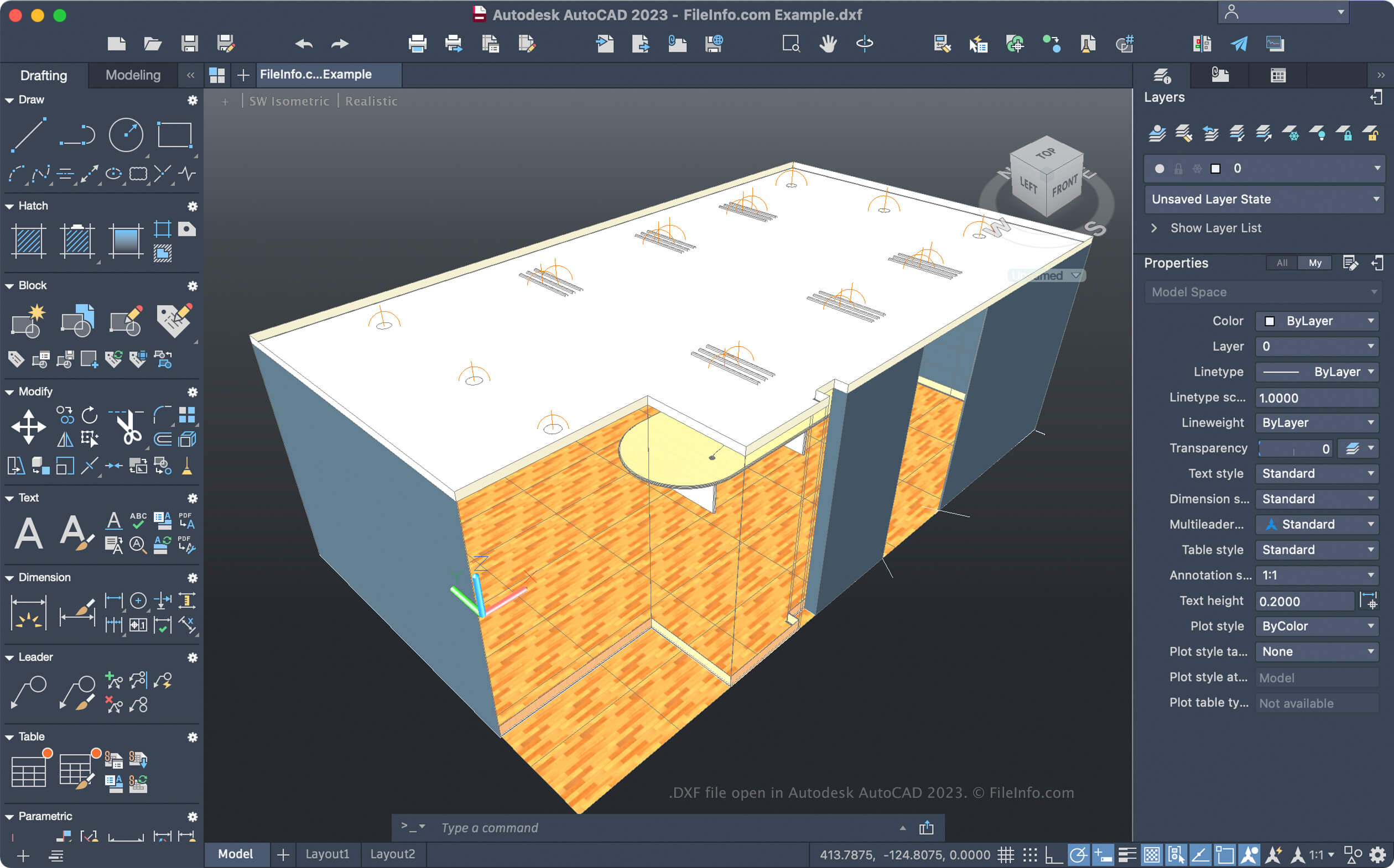
The DXF format was introduced by Autodesk in December 1982 as part of the initial release of AutoCAD. At the time, the CAD industry was fragmented, with various software packages utilizing proprietary formats that could not “talk” to one another. Autodesk’s decision to create a documented, open-access exchange format was a revolutionary move that prioritized cross-platform collaboration.
The Structural Framework of a DXF File
A DXF file is essentially a tagged data representation of a drawing. This means that every piece of information in the file is preceded by an integer called a “group code,” which indicates what type of data follows. This structured approach allows software to parse the file systematically.
A standard DXF file is divided into several key sections:
- Header Section: This contains the general variables of the drawing, such as coordinate systems, units of measurement, and versioning info.
- Classes Section: This holds the information for application-defined classes, which are necessary for handling complex object data.
- Tables Section: This defines named items such as line types, layers, text styles, and views.
- Blocks Section: This contains the definitions of entities that are grouped together to be reused throughout the drawing.
- Entities Section: This is the “meat” of the file, containing the actual drawing objects like lines, circles, arcs, and polylines.
- Objects Section: This includes non-graphical objects that provide additional data context.
ASCII vs. Binary DXF
Technologically, DXF exists in two primary forms: ASCII and Binary. The ASCII (American Standard Code for Information Interchange) version is the most common because it is human-readable. A developer can open an ASCII DXF in a simple text editor and see the coordinates and commands that form the drawing.
However, because ASCII files represent numbers as text strings, they can become incredibly large and slow to process. To combat this, the Binary DXF format was introduced. Binary DXF files are roughly 25% smaller and can be read and written much faster by computer systems. Despite the efficiency of binary, ASCII remains the gold standard for many because of its transparency and ease of debugging during the software development process.
Interoperability: Why DXF is Essential for the Tech Industry
The primary value proposition of DXF is its role as a universal translator. In a typical engineering workflow, a project might start in a specialized architectural program, move to a structural analysis tool, and finally end up in a CAM (Computer-Aided Manufacturing) software for fabrication. Without a neutral format like DXF, data would be lost at every transition.
Bridging the Gap Between CAD Platforms
Most professional design software—from high-end suites like SolidWorks and Rhino to open-source tools like LibreCAD—supports DXF. This ubiquity ensures that a designer is not “locked in” to a specific vendor’s ecosystem. For the tech industry, this promotes competition and innovation, as new software entrants can gain traction simply by ensuring they can accurately import and export DXF files.
Integration with Manufacturing and CNC Tech
The rise of the “Maker Movement” and the digital transformation of factories owe much to DXF. Computer Numerical Control (CNC) machines, laser cutters, and plasma cutters rely on precise vector paths to guide their tools. Because DXF stores information as mathematical vectors (points, lines, and curves) rather than pixels, it provides the exact coordinates these machines need to operate.
When a design is exported as a DXF, the CNC software interprets the entities as “toolpaths.” The precision of DXF ensures that a part designed to a tolerance of 0.001mm in a CAD program is manufactured to those exact specifications on the factory floor.
Technical Comparison: DXF vs. DWG and SVG
To truly appreciate the utility of DXF, it is helpful to compare it with other prominent vector formats used in technology today. While they may seem interchangeable to the uninitiated, their underlying structures and use cases differ significantly.
DXF vs. DWG: The Proprietary Battle
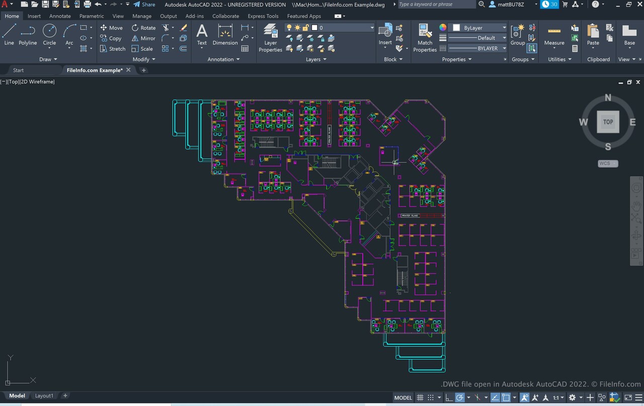
DWG (Drawing) is the native format for AutoCAD. It is a binary format that is much more “dense” than DXF, meaning it can store more complex data (like custom metadata and advanced 3D geometries) in a smaller file size. However, DWG is a closed, proprietary format. While other companies have reverse-engineered it, Autodesk frequently updates the DWG specification, making it difficult for third-party software to maintain perfect compatibility.
DXF, by contrast, is the “open” alternative. While it may not support every high-end feature found in the latest DWG version, its documentation is public. If a technician needs to ensure that a file will open correctly on a machine built 15 years ago or in a specialized niche software, DXF is the safer, more reliable choice.
DXF vs. SVG: Engineering vs. Web Design
Scalable Vector Graphics (SVG) is another popular vector format, primarily used in web development and graphic design. While both DXF and SVG represent shapes using mathematical paths, their “intent” is different.
- SVG is optimized for display. It includes support for color gradients, transparency, and animation, making it perfect for websites and UI/UX design.
- DXF is optimized for precision and engineering. It focuses on layers, precise measurements, and technical attributes. You wouldn’t use an SVG to program a 5-axis milling machine, and you wouldn’t use a DXF to create a responsive website logo.
Practical Workflows and Implementation Strategies
Implementing DXF into a professional workflow requires an understanding of how to manage data integrity. Because DXF is a “lowest common denominator” format, some information can be lost if the conversion isn’t handled correctly.
Optimizing Files for Conversion
When preparing a DXF for export, tech professionals must follow several best practices to ensure the file remains functional:
- Exploding Blocks: Some older CAM software cannot read “blocks” (grouped objects). Designers often need to “explode” these groups into individual lines and arcs before exporting.
- Managing Layers: DXF supports layers, which is crucial for manufacturing. For example, a laser cutter might use one layer for “engraving” and another for “cutting.” Organizing the DXF by layer allows the machine to distinguish between different operations.
- Unit Standardization: One common pitfall in DXF exchange is the “unitless” nature of some versions. A drawing made in millimeters might be interpreted as inches by another program. Explicitly setting and verifying units during the export process is a critical technical step.
Security and Integrity in DXF Sharing
In the realm of digital security, sharing DXF files requires caution. Because ASCII DXF files are plain text, they can be easily manipulated. Furthermore, DXF files can occasionally carry “bloat”—unnecessary metadata or “ghost” entities that increase file size and can potentially crash sensitive manufacturing software. Using “Purge” commands and auditing tools to clean a DXF before transmission is a standard procedure for maintaining technical data integrity.
The Future of the Drawing Exchange Format
As we move further into the era of AI-driven design and 3D printing, some have questioned whether the 40-year-old DXF format remains relevant. The reality is that while 3D-specific formats like STEP, IGES, and STL are dominant in additive manufacturing, the DXF format is evolving rather than disappearing.
From 2D Drafting to 3D Complexity
While DXF started as a 2D format, modern versions support 3D wireframes and surfaces. However, its primary strength remains in 2D and 2.5D applications (like flat-sheet cutting). In the world of “Industry 4.0,” where automation is key, the simplicity of DXF is actually its greatest asset. It provides a lightweight, easily parsed instruction set that doesn’t require massive computational overhead to process.
DXF in the Age of AI and Automation
Newer AI tools that generate CAD models often use DXF as their output format because of its structured nature. It is much easier to train an AI to generate a valid DXF text string than it is to have it compile a complex, proprietary binary DWG. As generative design becomes more prevalent, DXF will likely serve as the primary language through which AI designers communicate with human engineers and robotic fabricators.
In conclusion, DXF is the “unsung hero” of the technology world. It is the invisible thread that connects a sketch on a tablet to a finished steel component on a skyscraper. By providing a reliable, documented, and universal way to describe geometry, DXF has ensured that the digital world can always be translated into the physical one. Whether you are a software developer, a mechanical engineer, or a tech enthusiast, understanding DXF is essential to navigating the complex ecosystem of modern design and manufacturing.
aViewFromTheCave is a participant in the Amazon Services LLC Associates Program, an affiliate advertising program designed to provide a means for sites to earn advertising fees by advertising and linking to Amazon.com. Amazon, the Amazon logo, AmazonSupply, and the AmazonSupply logo are trademarks of Amazon.com, Inc. or its affiliates. As an Amazon Associate we earn affiliate commissions from qualifying purchases.