
Automotive technology has evolved significantly over the past few decades, transitioning from purely mechanical systems to complex, computer-driven ecosystems. Despite these advancements, the fundamental requirement for a direct current (DC) power source remains constant. The car battery is the heart of a vehicle’s electrical system, providing the necessary surge of energy to engage the starter motor and initialize the onboard diagnostics. However, when a battery fails, the solution often involves one of the oldest and most reliable hardware interfaces in the automotive world: jumper cables. To use this hardware safely and effectively, understanding the technical specifications of polarity is essential. Specifically, identifying which color corresponds to the positive terminal is the most critical step in the process.

The Color-Coding Standard in Automotive Hardware
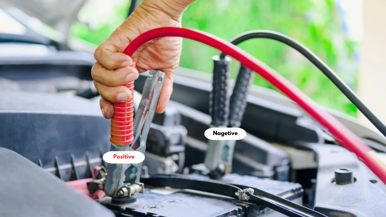
In the world of electrical engineering and automotive maintenance, standardization is the cornerstone of safety. The universal standard for jumper cables dictates that the red cable and its corresponding clamps are positive (+), while the black cable and its clamps are negative (-). This color-coding is not arbitrary; it is a global protocol designed to prevent catastrophic electrical failure and physical injury.
The positive terminal on a lead-acid battery is typically marked with a plus sign (+) and may feature a red plastic cover or a slightly larger diameter than the negative post. The red cable is designed to interface specifically with these positive terminals. On the other side of the circuit, the black cable represents the negative or “ground” connection. In modern automotive electrical architecture, the negative terminal is connected directly to the vehicle’s chassis, which acts as a common ground for the entire electrical system.
Understanding this hardware interface requires a basic grasp of DC circuit physics. Electricity flows from the positive terminal to the negative terminal. When you connect two batteries in parallel—which is what you are doing during a jump-start—you are effectively using the charged battery to supplement the voltage of the depleted one. If these cables are reversed (a condition known as reverse polarity), the result is a massive short circuit. This can lead to the melting of cable insulation, permanent damage to the vehicle’s alternator, and, in extreme cases, the explosion of the battery due to the rapid ignition of hydrogen gas.
Technical Procedure: The Algorithm of a Safe Jump-Start
Executing a jump-start is essentially a hardware integration process between two distinct power systems. To ensure the safety of the sensitive electronic control units (ECUs) found in modern vehicles, a specific technical sequence must be followed. This sequence is designed to minimize the risk of voltage spikes and sparking near the battery vents.
Preparing the Hardware Interface
Before any connections are made, ensure that both vehicles are positioned close enough for the cables to reach but are not physically touching. If the vehicles touch, it could create an unintended ground path, complicating the electrical flow. Ensure both vehicles are powered down, the ignitions are off, and the parking brakes are engaged.
The Connection Sequence
- Positive to Dead: Attach the first red (positive) clamp to the positive terminal of the dead battery. Ensure the metal teeth of the clamp have a firm, “low-resistance” grip on the terminal.
- Positive to Live: Attach the other end of the red (positive) cable to the positive terminal of the functioning (donor) battery.
- Negative to Live: Attach the first black (negative) clamp to the negative terminal of the functioning battery.
- Negative to Ground: This is the most misunderstood step in the tutorial. Instead of attaching the final black clamp to the negative terminal of the dead battery, you should attach it to an unpainted metal part of the engine block or the vehicle’s frame. This is known as a “remote ground.” By doing this, any sparks generated during the final connection occur away from the battery, reducing the risk of igniting hydrogen gas.
Initializing the System
Once the physical hardware link is established, start the engine of the donor vehicle and let it run for several minutes. This allows the alternator of the live vehicle to pass a “surface charge” to the dead battery. After a few minutes, attempt to start the vehicle with the dead battery. If it initializes, do not turn it off immediately. The vehicle needs time for its own alternator to begin the chemical process of recharging the internal lead plates.
Circuitry and Safety: Protecting Modern Vehicle Electronics
As vehicles have become more technologically advanced, they have also become more sensitive to electrical fluctuations. Modern cars are essentially “computers on wheels,” containing dozens of microprocessors that manage everything from fuel injection to infotainment systems. When you connect jumper cables, you are introducing a potential source of electromagnetic interference and high-voltage transients.
One of the primary risks during a jump-start is a voltage surge. When the dead engine finally turns over and the cables are disconnected, the sudden change in the electrical load can cause a spike in the system voltage. If this spike exceeds the tolerance of the vehicle’s semiconductors, it can “fry” the ECU. To mitigate this, many high-end jumper cables now come equipped with integrated surge protectors—small hardware modules that clamp the voltage to a safe level (usually around 14.8V or 15V).
Furthermore, the rise of hybrid and electric vehicles (EVs) has added a new layer of complexity. While most EVs still carry a 12V lead-acid battery to power onboard electronics and safety systems, the procedures for jumping these batteries differ significantly from traditional internal combustion engines. In many EVs, the 12V battery is not used to crank an engine but merely to close a high-voltage contactor. Using the wrong terminals or reversing the red and black cables in an EV environment can result in tens of thousands of dollars in damage to the DC-to-DC converter or the main lithium-ion traction battery.
The Evolution of Jump-Starting Tech: From Copper Cables to Portable Power Banks
The traditional copper-core jumper cable is a legacy technology that is slowly being supplemented, and in some cases replaced, by smarter, more portable gadgets. The most significant advancement in this niche is the lithium-ion portable jump starter.
These gadgets are essentially high-capacity power banks optimized for high-current discharge. Unlike traditional cables, which require a second “donor” vehicle, these portable units allow for a self-contained recovery. From a tech perspective, these devices are fascinating because they include “Smart Cables.” These smart interfaces utilize internal sensors and MOSFETs (Metal-Oxide-Semiconductor Field-Effect Transistors) to monitor the connection in real-time.
If a user accidentally connects the red clamp to a negative terminal, the device will detect the reverse polarity and refuse to send current, often alerting the user with an LED indicator or an audible alarm. This “failsafe” architecture removes the human error factor that makes traditional jumping dangerous. Additionally, these modern gadgets often include USB-C Power Delivery ports, integrated LED work lights, and digital displays that report the exact voltage of the vehicle’s battery, providing a diagnostic layer that simple cables cannot offer.

Battery Management Systems and Predictive Maintenance
The best way to handle a dead battery is to prevent it through the use of diagnostic technology. Modern Battery Management Systems (BMS) are designed to monitor the State of Health (SoH) and State of Charge (SoC) of the battery constantly. Many new vehicles offer mobile app integration that sends a push notification to the owner’s smartphone if the battery voltage drops below a certain threshold.
For enthusiasts and those who maintain multiple vehicles, digital battery testers have become essential gadgets. These tools use “conductance testing” technology to determine the internal resistance of the battery. By sending a small frequency through the plates, the device can calculate the remaining Cold Cranking Amps (CCA) available. This data allows a user to identify a failing battery months before it actually leaves them stranded.
In the digital age, even the simple act of identifying a red cable as positive is part of a broader interaction with hardware and software. Whether you are using a heavy-duty set of 4-gauge copper cables or a high-tech lithium-ion booster pack, the principle remains the same: the red connection is the gateway for positive energy. By respecting the polarity and understanding the technical risks involved with modern automotive circuitry, you can navigate the challenges of vehicle maintenance with professional precision and technical insight. As we move toward a future of solid-state batteries and even more advanced vehicle architectures, the fundamental logic of the positive/negative circuit will remain the bedrock of mobile power technology.
aViewFromTheCave is a participant in the Amazon Services LLC Associates Program, an affiliate advertising program designed to provide a means for sites to earn advertising fees by advertising and linking to Amazon.com. Amazon, the Amazon logo, AmazonSupply, and the AmazonSupply logo are trademarks of Amazon.com, Inc. or its affiliates. As an Amazon Associate we earn affiliate commissions from qualifying purchases.