
The Raspberry Pi has established itself as a cornerstone in the world of single-board computing, empowering countless projects from home automation to industrial control. A critical component enabling this versatility is its General Purpose Input/Output (GPIO) header. For anyone looking to interface with the Raspberry Pi, understanding the specifications of these headers, particularly their pitch, is fundamental. The Raspberry Pi primarily utilizes 2.54mm (0.1-inch) pitch headers. This choice is not arbitrary; it’s a deliberate embrace of an industry standard that significantly contributes to the platform’s accessibility and vast ecosystem.
The Ubiquitous 2.54mm GPIO Header
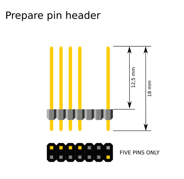
The 2.54mm pitch, often referred to as 0.1-inch in imperial units, is the standard spacing between pins on the Raspberry Pi’s main GPIO header. This seemingly minor detail holds immense importance for makers, educators, and engineers alike.
A Standard in Prototyping and Hobbyist Electronics
The 2.54mm pitch has been a de facto standard in electronics prototyping for decades. Its origins can be traced back to early integrated circuits (ICs) and the need for a universally compatible connection method.
- Breadboard Compatibility: The most significant advantage of the 2.54mm pitch is its perfect alignment with standard breadboards. These invaluable tools for rapid prototyping feature rows of holes spaced exactly 2.54mm apart, allowing components and jumper wires to be easily inserted and reconfigured without soldering. This makes the Raspberry Pi immediately compatible with a vast array of existing electronic components and development tools.
- Ease of Soldering and Prototyping: For permanent connections, the 2.54mm pitch provides ample space between pins, making it relatively easy to solder connections manually, even for beginners. This contrasts sharply with finer pitch connectors found in more advanced surface-mount technology (SMT), which often require specialized equipment and expertise.
- Widespread Component Availability: The adherence to this standard means that a massive ecosystem of sensors, actuators, breakout boards, and modules are manufactured with 2.54mm pitch pins or compatible connectors. This broad availability lowers the barrier to entry for new projects and allows for greater design flexibility.
Physical Dimensions and Pin Count Variations
While the pitch remains consistent across most models, the physical length and pin count of the GPIO header have evolved with different Raspberry Pi iterations.
- Early Models (26-pin): The very first Raspberry Pi models, such as the Raspberry Pi 1 Model B and Model A, featured a 26-pin (2×13) GPIO header. This provided a foundational set of digital I/O, power, and ground pins sufficient for many basic projects.
- Modern Models (40-pin): Starting with the Raspberry Pi 1 Model B+ and continuing through the Raspberry Pi 2, 3, 4, and the latest Raspberry Pi 5, the standard GPIO header expanded to 40 pins (2×20). This significantly increased the number of available GPIO pins, as well as dedicated pins for specific functions like I2C, SPI, UART, and PWM, opening up a much wider range of complex projects and peripheral integrations. The pin numbering and functions are largely backward compatible for the first 26 pins, meaning older HATs (Hardware Attached on Top) could still function, albeit without access to the additional pins.
- Raspberry Pi Zero Series: The diminutive Raspberry Pi Zero and Zero W/2W models are unique in that they often come with an unpopulated 40-pin header. To save space and cost, users typically need to solder their own 2.54mm male or female headers onto the board if they wish to use the GPIO pins. This design choice highlights the trade-off between miniaturization and immediate plug-and-play capability.
Always consult the official pinout diagrams for your specific Raspberry Pi model to ensure correct connections, as pin assignments can vary slightly or offer different functionalities.
Understanding the GPIO Pinout and Its Significance
The 40-pin GPIO header is far more than just a collection of simple on/off switches. It is a sophisticated interface that allows the Raspberry Pi to communicate with and control a vast array of external components. Understanding the pinout is crucial for harnessing the full potential of your device.
Beyond Simple Connections: Multifunctionality
Each pin on the GPIO header can often serve multiple purposes, making the Raspberry Pi incredibly versatile.
- General Purpose Input/Output (GPIO): At their core, these pins can be configured as either inputs (to read signals from sensors, buttons, etc.) or outputs (to control LEDs, relays, motors, etc.). They operate at a 3.3V logic level.
- Power and Ground: Essential for powering external components, the header includes multiple 5V and 3.3V power pins, as well as several ground (GND) pins. These allow for direct power supply to low-power peripherals without needing an external power source for each.
- Serial Communication Interfaces:
- UART (Universal Asynchronous Receiver/Transmitter): Typically TXD (transmit) and RXD (receive) pins, enabling serial communication with devices like GPS modules, Bluetooth modules, or other microcontrollers.
- I2C (Inter-Integrated Circuit): A two-wire serial bus (SDA for data, SCL for clock) used for connecting to a wide range of devices such as EEPROMs, real-time clocks, and various sensors (accelerometers, gyroscopes). Multiple I2C buses might be available on newer Pi models.
- SPI (Serial Peripheral Interface): A synchronous serial communication interface (typically MOSI, MISO, SCLK, and CE pins) often used for higher-speed communication with devices like displays, SD card readers, and analog-to-digital converters (ADCs).
- PWM (Pulse Width Modulation): Some GPIO pins can be configured to output PWM signals, which are essential for controlling the speed of motors, dimming LEDs, or generating specific analog-like outputs from a digital pin.
It is imperative to refer to the specific pinout diagram for your Raspberry Pi model to correctly identify the function of each pin. Misconnecting pins, especially power and ground, can damage the Raspberry Pi or the attached components.
Powering Peripherals and Sensing Data

The GPIO header serves as the primary gateway for the Raspberry Pi to interact with the physical world.
- Powering Modules: The 5V and 3.3V pins provide regulated power to external modules. While convenient, it’s important to be aware of the current limitations. The 3.3V rail typically has a lower current capacity than the 5V rail. For high-current devices, an external power supply or a powered USB hub may be necessary.
- Connecting Sensors: Digital sensors directly interface with GPIO pins as inputs, while analog sensors require an Analog-to-Digital Converter (ADC), which can communicate with the Pi via SPI or I2C.
- Controlling Actuators: LEDs, buzzers, relays, and small motors can be directly controlled via GPIO output pins, often with the addition of current-limiting resistors or driver circuits for higher current loads.
- Logic Level Compatibility: A crucial consideration is that the Raspberry Pi’s GPIO pins operate at 3.3V logic. Connecting a 5V logic device directly to a 3.3V input pin can damage the Pi. In such cases, a logic level shifter is required to safely translate between different voltage levels.
Connecting to the Raspberry Pi’s Headers: Tools and Techniques
Leveraging the 2.54mm GPIO header effectively involves a variety of tools and connection methods, depending on the project’s complexity and permanence.
Prototyping with Breadboards and Jumper Wires
For initial experimentation and temporary circuits, breadboards are indispensable.
- Standard Breadboards: These boards feature rows of holes spaced at 2.54mm, perfectly matching the Pi’s header. Components can be pushed into these holes to make electrical connections.
- Jumper Wires: These flexible wires, with 2.54mm pitch connectors at their ends, are used to connect the Raspberry Pi’s GPIO pins to breadboards or directly to other components. They come in three common types:
- Male-to-Male: Used for connecting holes on a breadboard or between two female headers.
- Male-to-Female: Most commonly used to connect the male pins of the Raspberry Pi’s header to the holes on a breadboard or to female headers on modules.
- Female-to-Female: Used to connect two sets of male pins or between two modules with male headers.
Always ensure jumper wires are correctly inserted and that their insulation prevents accidental short circuits.
Integrating with HATs and pHATs
The Raspberry Pi ecosystem boasts an extensive range of add-on boards known as HATs (Hardware Attached on Top) and their smaller counterparts, pHATs (partial HATs).
- HAT Specification: HATs are specifically designed to sit directly on top of the Raspberry Pi, connecting via the 40-pin GPIO header. They adhere to a formal specification that includes board dimensions, pin usage, and crucially, an EEPROM (Electrically Erasable Programmable Read-Only Memory). This EEPROM allows the Raspberry Pi to automatically identify the HAT and load necessary drivers or configuration settings, simplifying setup.
- Mechanical Stability: HATs often come with standoffs to ensure mechanical stability, preventing them from wiggling or shorting components on the Pi.
- Functionality Expansion: HATs provide a straightforward way to add significant functionality, such as motor drivers, DACs/ADCs, display interfaces, power management, or specialized sensor arrays, without complex wiring.
Soldering and Custom Connections
While breadboards and HATs cover many scenarios, custom solutions sometimes require direct soldering.
- Unpopulated Headers (e.g., Pi Zero): For models like the Raspberry Pi Zero, soldering a 2.54mm male or female header onto the board is often the first step to enable GPIO access.
- Custom PCBs: For more permanent or integrated projects, custom Printed Circuit Boards (PCBs) can be designed to interface directly with the Raspberry Pi’s 2.54mm header. This allows for compact and robust designs tailored to specific applications.
- Ribbon Cables: For connections that require routing signals away from the Pi, 2.54mm pitch IDC (Insulation Displacement Connector) ribbon cables are a popular choice. These cables can be crimped onto IDC connectors that plug directly into the GPIO header, providing a neat and reliable multi-wire connection to breakout boards or custom interfaces.
Future Trends and Header Evolution
The 2.54mm header’s enduring presence on the Raspberry Pi is a testament to its practical advantages, particularly in an ecosystem driven by hobbyists and rapid prototyping.
Continuing the 2.54mm Tradition
The likelihood of the Raspberry Pi Foundation abandoning the 2.54mm pitch for its primary GPIO header in mainstream models is low.
- Ecosystem Inertia: The sheer volume of existing HATs, modules, and accessories designed for this standard creates significant inertia. A shift would fragment the ecosystem and impose compatibility challenges on millions of users and developers.
- Maker-Centric Design: The Raspberry Pi’s success is rooted in its accessibility. The 2.54mm pitch contributes significantly to this by facilitating easy breadboard prototyping and manual wiring, which are core activities for its target audience of makers, educators, and embedded developers.
- Sufficient Pin Density: For most general-purpose I/O tasks, the 40-pin 2.54mm header offers a good balance between pin density and ease of use.
Specialized Connectors for Advanced Interfaces
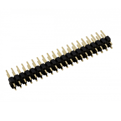
While the GPIO header retains its traditional pitch, the Raspberry Pi series has progressively introduced other, finer-pitch connectors for specialized, high-speed interfaces.
- CSI and DSI Connectors: These tiny, flat flexible cable (FFC) connectors (typically 0.5mm or 1.0mm pitch) are dedicated to the Camera Serial Interface (CSI) and Display Serial Interface (DSI) respectively. They handle high-bandwidth video and display data, which would be impractical over standard GPIO pins.
- PCIe on Raspberry Pi 5: The latest Raspberry Pi 5 introduces a single-lane PCI Express 2.0 interface via a dedicated, much finer-pitch FPC connector. This allows for high-speed peripheral expansion, like NVMe SSDs, requiring an entirely different class of electrical signal integrity and connector design than general-purpose GPIO. These specialized connectors do not replace the GPIO header but augment the Pi’s capabilities for advanced applications.
In conclusion, the 2.54mm (0.1-inch) pitch header is a defining characteristic of the Raspberry Pi’s GPIO interface, underpinning its compatibility with a vast world of electronics. This deliberate choice prioritizes ease of use, prototyping flexibility, and ecosystem growth, ensuring the Raspberry Pi remains a go-to platform for innovation and learning. While advanced interfaces might introduce finer-pitch connectors for specific high-bandwidth needs, the familiar 2.54mm header remains the heart of the Raspberry Pi’s general-purpose interaction with external hardware.
aViewFromTheCave is a participant in the Amazon Services LLC Associates Program, an affiliate advertising program designed to provide a means for sites to earn advertising fees by advertising and linking to Amazon.com. Amazon, the Amazon logo, AmazonSupply, and the AmazonSupply logo are trademarks of Amazon.com, Inc. or its affiliates. As an Amazon Associate we earn affiliate commissions from qualifying purchases.