
In the intricate world of technology, where every circuit, sensor, and power line plays a critical role, understanding the fundamental properties of the components involved is paramount. Among these, the seemingly simple “wire” holds a position of immense importance. But a wire is not just a wire; its capabilities and limitations are largely defined by a crucial characteristic: its gauge. For anyone involved in electronics, electrical engineering, networking, or even just setting up a smart home, comprehending wire gauge is not merely a technical detail; it’s a cornerstone for safety, efficiency, and optimal performance.
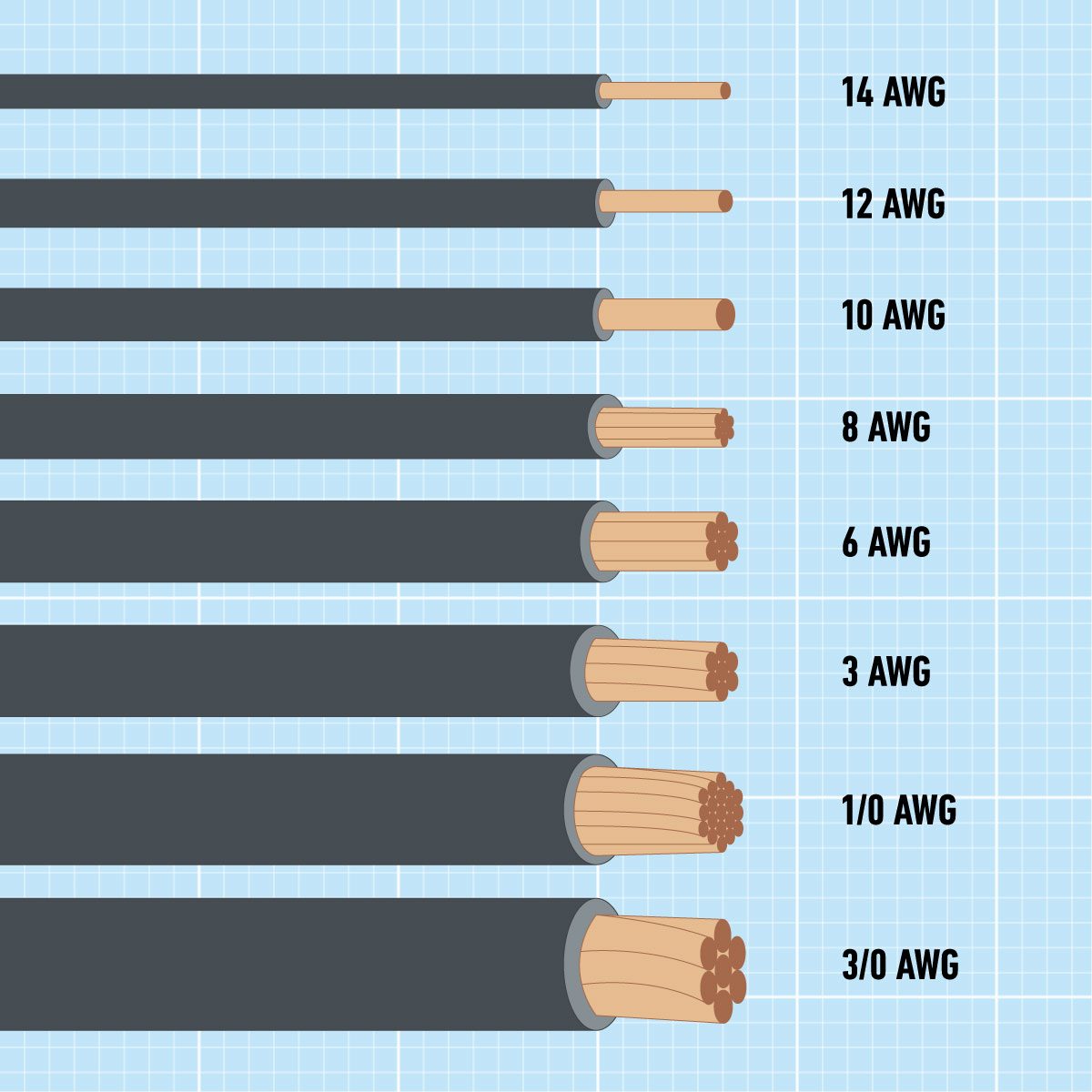
Wire gauge refers to the measurement of a wire’s diameter. This seemingly straightforward dimension dictates a host of critical properties, including its electrical resistance, current-carrying capacity, weight, and even its mechanical strength. From the microscopic traces on a printed circuit board to the robust cables powering industrial machinery, the principles of wire gauge are consistently applied. Choosing the correct gauge is essential to prevent overheating, minimize voltage drop, ensure reliable data transmission, and ultimately, guarantee the longevity and safety of any electrical or electronic system. Without a clear grasp of wire gauge, engineers risk system failures, safety hazards, and suboptimal performance – issues that no modern technological application can afford.
Understanding Wire Gauge: The Foundation of Electrical Design
The physical dimension of a wire’s conductor is perhaps its most defining characteristic, directly influencing how it performs in an electrical circuit. Far from being an arbitrary number, wire gauge is a standardized measurement that underpins the design, installation, and troubleshooting of virtually all electrical and electronic systems. Its importance cannot be overstated in a world increasingly reliant on precise and reliable connectivity.
The Basics of Wire Gauge Measurement
At its core, wire gauge quantifies the cross-sectional area of the conductive metal within a wire. This area is inversely proportional to the wire’s gauge number in most common systems, meaning a smaller gauge number indicates a larger diameter wire. This inverse relationship can sometimes be a source of initial confusion but is quickly understood in context. The material of the conductor (typically copper or aluminum) also plays a role, as different metals have different conductivities, but the physical size remains the primary determinant of current capacity for a given material.
The larger the cross-sectional area, the more “room” electrons have to flow, reducing resistance and allowing for higher current loads. Conversely, a thinner wire (higher gauge number) offers more resistance per unit length and can only safely carry smaller currents. Measuring wire gauge accurately involves specialized tools like wire gauge charts, micrometers, or even dedicated wire gauge calipers, though for common applications, the gauge is typically printed on the wire’s insulation or specified in product documentation.
Why Wire Gauge Matters in Tech
In the rapidly evolving landscape of technology, the precise selection of wire gauge is a non-negotiable aspect of design and implementation. Its implications touch upon almost every facet of electrical and electronic engineering:
- Safety: Overloaded wires are a significant fire hazard. A wire too thin for the current it carries will heat up excessively, melting insulation, causing short circuits, and potentially igniting surrounding materials. Proper gauge selection ensures the wire remains within safe operating temperatures.
- Performance:
- Voltage Drop: Thinner wires have higher electrical resistance. When current flows through them, some electrical energy is dissipated as heat, leading to a drop in voltage along the wire’s length. For sensitive electronics, motor control, or long power runs, excessive voltage drop can impair device functionality or reduce efficiency.
- Current-Carrying Capacity (Ampacity): Every wire gauge has a maximum safe current it can carry without overheating, known as its ampacity. Exceeding this limit is not only a safety risk but also degrades the wire and connected components over time.
- Data Integrity: In networking and data transmission, while not solely determined by gauge, the electrical properties influenced by gauge (like resistance and capacitance) can affect signal attenuation and interference, impacting data speed and reliability, especially for analog signals or high-power PoE (Power over Ethernet) applications.
- Cost and Efficiency: Using an unnecessarily thick wire (lower gauge) for an application increases material costs, makes installation more difficult due to reduced flexibility, and adds weight. Conversely, undersizing can lead to frequent replacements, higher energy losses, and system failures, ultimately increasing long-term costs.
- Compatibility: Ensuring that wires fit connectors, terminals, and conduits correctly often depends on their precise diameter, which is a direct outcome of their gauge.
The American Wire Gauge (AWG) System: A Global Standard
While various systems for measuring wire exist, the American Wire Gauge (AWG) system has become the predominant standard, particularly in North America, and is widely recognized and used in many technical specifications globally. Its systematic approach to sizing electrical conductors provides a consistent framework for engineers and technicians.
How AWG Numbers Relate to Wire Diameter
The AWG system is unique in its inverse relationship between the gauge number and the wire’s diameter. It is based on a logarithmic scale, derived from the number of drawing operations needed to produce a specific wire size.
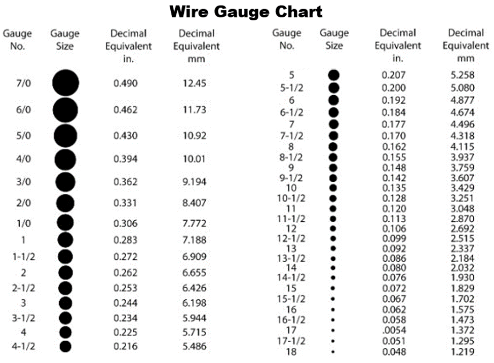
- Inverse Relationship: A smaller AWG number indicates a larger wire diameter and thus a larger cross-sectional area. For example, 10 AWG wire is much thicker than 20 AWG wire.
- Doubling and Halving: A key characteristic of the AWG system is that a difference of three AWG numbers approximately doubles or halves the cross-sectional area. For instance, an 18 AWG wire has roughly twice the cross-sectional area of a 21 AWG wire, and conversely, 15 AWG has about half the area of 12 AWG. Similarly, a change of 6 AWG numbers roughly doubles or halves the diameter.
- The Zero Gauge and Beyond: The AWG scale includes gauge sizes from 0000 (4/0) down to 40 AWG and even finer. 4/0 AWG is a very thick wire, while 40 AWG is extremely thin, often used in precision coils or small electronic components.
Understanding this numbering convention is crucial for quickly assessing a wire’s physical properties and its suitability for a given task. Wire gauge charts are invaluable tools, providing precise diameter measurements (in inches or millimeters) and corresponding cross-sectional areas for each AWG size.
Implications of AWG on Current Carrying Capacity
The most direct and critical implication of an AWG number is its impact on a wire’s ampacity, or its maximum safe current-carrying capacity. This is directly related to the wire’s resistance, which in turn is determined by its cross-sectional area.
- Resistance and Heat: A larger diameter wire (lower AWG number) has less resistance per unit length. When current flows, the power dissipated as heat is proportional to I²R (current squared times resistance). Less resistance means less heat generated for a given current.
- Ampacity Ratings: Electrical codes (like the National Electrical Code in the US) and industry standards provide detailed tables for the ampacity of different AWG wires, typically for copper and aluminum conductors, and sometimes varying based on insulation type and ambient temperature. These tables are vital for designing safe and compliant electrical installations.
- Voltage Drop Considerations: As discussed, resistance also leads to voltage drop. For longer wire runs, even a properly sized wire for ampacity might experience significant voltage drop that impacts device performance. Lower AWG wires are often chosen for longer runs or higher power applications to minimize this effect, even if a higher AWG wire could technically handle the current without overheating.
- Temperature Rating: The insulation material around the conductor also has a temperature rating. While the gauge dictates how much heat the conductor itself generates, the insulation must be able to withstand that heat safely. Wires with higher temperature-rated insulation can sometimes carry slightly more current for the same gauge, within specific application limits.
The AWG system provides a standardized language for specifying these critical electrical properties, ensuring that components are correctly matched and systems operate reliably and safely across a multitude of technological applications, from consumer electronics to industrial control systems.
Diverse Wire Types and Their Gauge Considerations in Tech
While the AWG system provides a universal language for wire diameter, the practical application of wire gauge in technology is further nuanced by the physical construction and specialized design of different wire types. The choice between solid and stranded, or the integration of shielding and high-temperature insulation, all interact with the fundamental concept of gauge to meet specific technological demands.
Solid vs. Stranded Wire: Performance and Flexibility
The internal structure of a wire, particularly whether it’s a single solid conductor or composed of multiple thinner strands, significantly impacts its usability and performance, even if the overall gauge (cross-sectional area) remains the same.
- Solid Core Wire:
- Construction: Consists of a single, thick conductor.
- Advantages: Lower resistance per unit length (for the same gauge) compared to stranded wire due to less “air space” between conductors, making it slightly better for signal integrity in some high-frequency applications. More mechanically rigid, making it easier to push through conduits and ideal for fixed installations or breadboards where frequent movement is not required. Typically cheaper to manufacture.
- Disadvantages: Less flexible and prone to breaking if bent repeatedly. Harder to terminate in some connectors.
- Tech Applications: In-wall wiring, telecom backbone cabling (e.g., Cat5e/6 in fixed runs), breadboard prototyping, and permanent installations where flexibility is not a concern.
- Stranded Wire:
- Construction: Composed of numerous thin strands twisted together, forming a conductor whose overall cross-sectional area matches a specific gauge. For example, a 16 AWG stranded wire might be made of 26 individual 30 AWG strands.
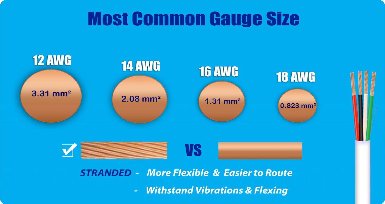
- Advantages: Significantly more flexible and resistant to fatigue from repeated bending. Easier to route and manage in complex enclosures. Better for applications requiring movement or vibration.
- Disadvantages: Slightly higher resistance for the same gauge due to skin effect at high frequencies and minor resistive losses between strands. Can be more challenging to terminate without proper crimping tools, as stray strands can cause shorts.
- Tech Applications: Patch cables (Ethernet, USB, HDMI), power cords for appliances, internal wiring in robotics and machinery, automotive wiring, and any application where flexibility and durability against movement are critical.
When selecting wire for a specific tech project, understanding whether solid or stranded is appropriate for the intended use and environment is as crucial as selecting the correct gauge.
High-Temperature and Shielded Wires: Gauge in Harsh Environments
Beyond basic conductivity, modern technological environments often demand wires with specialized properties to cope with extreme conditions or to protect signal integrity. The gauge selection still applies, but these specialized features add layers of consideration.
- High-Temperature Wires:
- Purpose: Designed to operate safely in environments where ambient temperatures are elevated, or where the wire itself is expected to generate significant heat (e.g., inside power supplies, motors, heating elements).
- Gauge Consideration: While the gauge determines the current-carrying capacity, high-temperature wires employ insulation materials (like silicone, PTFE, or fiberglass) that can withstand temperatures far beyond the typical 60°C or 90°C ratings of standard PVC insulation. This allows the wire to carry its rated current in hot environments without the insulation degrading.
- Tech Applications: Industrial machinery, aerospace, automotive engine compartments, ovens, and high-power electronic devices.
- Shielded Wires:
- Purpose: To protect sensitive signals from external electromagnetic interference (EMI) or radio frequency interference (RFI), and conversely, to prevent signals within the wire from emitting interference.
- Gauge Consideration: The gauge applies to the central conductor(s) carrying the primary signal or power. The shielding (typically a braid, foil, or both, often connected to ground) is an additional layer, not directly part of the gauge measurement of the primary conductors. However, the overall cable diameter and flexibility are affected by the presence of shielding.
- Types of Shielding:
- Foil Shielding: Provides 100% coverage and is effective against high-frequency interference.
- Braided Shielding: Offers good low-frequency protection and better mechanical strength/flexibility.
- Combination Shields: Utilize both foil and braid for comprehensive protection.
- Tech Applications: Audio/video cables (HDMI, XLR, instrument cables), data communication cables (USB, Ethernet), medical equipment, instrumentation, and any application where signal integrity is paramount in electrically noisy environments.
Understanding these specialized wire types and how their features interact with the fundamental concept of gauge allows for the robust and reliable design of technological systems that can withstand diverse operational challenges.
Practical Applications and Common Mistakes in Wire Gauge Selection
The theoretical understanding of wire gauge translates into critical practical decisions in every technology domain. Incorrect gauge selection is a prevalent cause of system failures, safety hazards, and suboptimal performance. Avoiding these pitfalls requires careful consideration of the specific application, environment, and electrical demands.
Preventing Overheating and Voltage Drop
These are two of the most critical issues directly addressed by correct wire gauge selection. Failing to account for either can have severe consequences.
- Overheating: This occurs when a wire carries more current than its ampacity rating. The excess electrical energy is converted into heat, raising the wire’s temperature.
- Prevention: Always consult ampacity tables (e.g., NEC tables in the US) that specify the maximum current for a given wire gauge, conductor material (copper vs. aluminum), insulation temperature rating, and installation method (e.g., in conduit, free air). Factor in derating requirements for bundles of wires or high ambient temperatures. For example, a 14 AWG copper wire might be rated for 15 amps, while a 12 AWG is rated for 20 amps. Using 14 AWG for a 20-amp circuit is a fire hazard.
- Impact in Tech: Can melt insulation, damage connected electronic components, cause intermittent operation, and lead to electrical fires.
- Voltage Drop: As current flows through a wire, its inherent resistance causes a reduction in voltage from the source to the load. While not directly a safety hazard (unless it causes devices to malfunction in dangerous ways), excessive voltage drop significantly impairs performance.
- Prevention: Use voltage drop calculators or formulas. These typically require the current, the length of the wire run, and the conductor material. The goal is often to keep voltage drop below 3% (or even less for sensitive electronics) of the supply voltage. For longer runs or higher currents, a larger gauge (smaller AWG number) is necessary, even if a smaller gauge might technically meet the ampacity requirement. For instance, powering an outdoor camera over a long PoE run might require a higher gauge (lower AWG) Ethernet cable than a short indoor run, not just for data, but to ensure sufficient power reaches the device.
- Impact in Tech: Motors run slower or burn out, LED lights dim, sensitive electronics malfunction or behave erratically, charging times increase, and overall system efficiency plummets.
Optimizing for Data Transfer and Power Efficiency
In modern tech, wires often serve a dual purpose: transmitting power and data. Gauge selection plays a role in both, influencing the overall efficiency and reliability of a system.
- Data Transfer: While high-speed digital data transmission heavily relies on cable construction (e.g., twisted pairs in Ethernet, impedance control in coaxial cables), the gauge of the individual conductors still matters, particularly for signal attenuation over distance. Thinner wires have higher resistance and capacitance, which can degrade high-frequency signals, leading to slower speeds, increased error rates, and shorter maximum cable lengths. For high-bandwidth applications, slightly thicker conductors are often preferred where space permits.
- Power over Ethernet (PoE): PoE standards deliver both power and data over the same Ethernet cable. Here, the gauge of the twisted pairs is critical. Thicker conductors (e.g., 23 AWG in Cat6 or Cat6a vs. 24 AWG in Cat5e) reduce resistance, allowing more power to be delivered with less heat dissipation and voltage drop over longer distances. This is crucial for powering IP cameras, Wi-Fi access points, and smart lighting via PoE.
- Power Efficiency: By selecting the correct gauge, energy losses due to resistance (I²R losses) are minimized. This not only reduces electricity bills but also lessens the thermal load on the system, potentially extending the lifespan of components. In battery-powered devices, efficient wiring extends battery life.
Tools and Resources for Accurate Gauge Selection
Several resources are available to assist in making the right wire gauge choices:
- Wire Gauge Charts: Provide physical dimensions, resistance per foot, and often preliminary ampacity ratings for various AWG sizes.
- Ampacity Tables: Published by national electrical codes (e.g., NEC) and industry organizations, these are the authoritative source for safe current limits under specific conditions.
- Voltage Drop Calculators: Online tools and software that compute voltage drop based on current, length, voltage, and wire material/gauge.
- Manufacturer Specifications: Always refer to the specifications provided by equipment manufacturers for recommended wire gauges for their products.
- Multimeters and Wire Strippers/Crimpers: Essential tools for working with wires, ensuring proper termination and verification. Wire strippers often have gauge markings to help with correct stripping depth.
By diligently using these resources and understanding the underlying principles, engineers and technicians can ensure that their wire gauge selections lead to safe, efficient, and high-performing technological systems.
The Future of Wire Gauge and Connectivity
As technology continues its relentless march towards greater complexity, miniaturization, and higher demands for power and data, the fundamental principles of wire gauge remain relevant, albeit within increasingly sophisticated contexts. The future of connectivity will push the boundaries of materials science and design, but the core need for efficient and safe electrical conduction will persist.
Miniaturization and High-Density Wiring
The trend towards smaller, more powerful devices necessitates increasingly fine wires and higher-density wiring solutions.
- Challenges: As devices shrink (e.g., wearables, IoT sensors, high-density PCBs), space for wiring becomes extremely limited. This drives the use of very high AWG wires (smaller diameter) which present challenges in terms of current capacity, thermal management, and mechanical fragility.
- Innovations:
- Advanced Insulation Materials: Thinner, yet more robust and higher-temperature-rated insulation allows wires to be packed closer together without compromising safety or signal integrity.
- Flexible Printed Circuits (FPCs) and Flex-Rigid Boards: These effectively integrate very fine “wires” (traces) directly into the circuit board structure, often eliminating the need for discrete wires in tightly packed spaces.
- Lithography and Nanoscale Fabrication: For internal chip interconnects, the “wires” are now at the nanometer scale, pushing beyond traditional gauge concepts but adhering to the same physics of resistance and current limits.
- Impact: Enables the development of ultra-compact and lightweight devices, but demands precision engineering and materials science to manage heat dissipation and maintain signal quality.
Smart Grids and Renewable Energy Demands
The modernization of power infrastructure and the rise of renewable energy sources introduce new challenges and requirements for wire gauge in large-scale applications.
- Smart Grids: These intelligent grids require robust data communication alongside power transmission. This means integrated cabling solutions, often combining high-gauge power conductors with shielded data pairs or fiber optics, all designed to withstand harsh outdoor conditions and long distances.
- Renewable Energy (Solar, Wind, EV Charging):
- High Current DC Applications: Solar arrays and EV charging stations involve significant DC currents. DC resistance calculations and voltage drop considerations are paramount, as DC does not benefit from the “skin effect” that slightly increases AC resistance in large conductors. This often necessitates thicker wires (lower AWG) for efficient power transfer and minimal loss.
- Extreme Environments: Wires for wind turbines or solar farms must withstand severe weather, UV radiation, and temperature extremes, requiring specialized insulation and robust construction in conjunction with appropriate gauge selection.
- Energy Storage: Large-scale battery banks for grid stabilization or residential backup demand heavy-gauge interconnections to handle high discharge/charge currents.
- Impact: Drives innovation in high-capacity, durable, and integrated cabling systems, ensuring efficient energy transmission and robust data flow across vast and complex networks.
In conclusion, while the core definition of “what is the gauge of wire” remains constant, its implications continue to expand and deepen with technological advancements. From the smallest wearable device to the largest smart grid, precise wire gauge selection, influenced by evolving materials and applications, will remain a critical determinant of performance, safety, and the very feasibility of future technological innovations. Understanding this fundamental concept is not just about wires; it’s about mastering the conduits of our connected future.
aViewFromTheCave is a participant in the Amazon Services LLC Associates Program, an affiliate advertising program designed to provide a means for sites to earn advertising fees by advertising and linking to Amazon.com. Amazon, the Amazon logo, AmazonSupply, and the AmazonSupply logo are trademarks of Amazon.com, Inc. or its affiliates. As an Amazon Associate we earn affiliate commissions from qualifying purchases.