
In the modern automotive landscape, the dashboard serves as a sophisticated human-machine interface (HMI), acting as the primary communication hub between a vehicle’s complex internal computer systems and the driver. Among the array of icons, gauges, and digital readouts, the alternator warning light—often depicted as a stylized red battery symbol—is one of the most critical indicators of a vehicle’s electrical health. While many drivers mistake this icon for a simple battery life indicator, it actually signals a failure within the broader charging system technology. Understanding the engineering, sensor logic, and diagnostic implications of this light is essential for anyone navigating the intersection of hardware and software in contemporary transportation.

The Engineering Behind the Automotive Charging Ecosystem
To understand why the alternator warning light illuminates, one must first grasp the technological framework of the vehicle’s charging system. In a traditional internal combustion engine (ICE) vehicle, the alternator functions as a miniature power plant. It utilizes electromagnetic induction to convert mechanical energy from the engine’s crankshaft into electrical energy.
The Alternator as a Power Generator
At its core, the alternator is an electromechanical device consisting of a rotor, a stator, and a diode bridge. As the engine runs, a serpentine belt spins the rotor—an electromagnet—inside the stationary coils of the stator. This movement generates an alternating current (AC). However, automotive electronics, including the infotainment system, Engine Control Units (ECUs), and lighting, require direct current (DC). This is where the diode bridge, or rectifier, comes into play, converting AC to DC to power the vehicle and recharge the battery.
The Role of the Voltage Regulator
The voltage regulator is the “smart” component of the alternator. It monitors the electrical load and ensures the output remains within a specific range, typically between 13.5 and 14.5 volts. Without this regulation, a surge in engine RPM could lead to overvoltage, potentially frying sensitive semiconductors and digital displays. Conversely, if the voltage drops too low, the battery will deplete. The alternator warning light is the visual output of this regulator’s monitoring process; when the detected voltage deviates from the programmed parameters, the circuit is completed, and the light is triggered.
The Tech of Detection: Sensors, Circuits, and Data Paths
The transition from purely mechanical vehicles to “computers on wheels” has fundamentally changed how the alternator warning light functions. In older vehicles, the light was part of a simple series circuit. Today, it is a sophisticated data point integrated into the vehicle’s Controller Area Network (CAN bus).
Closed-Loop Circuitry and Resistance
In classic electrical architecture, the warning light is wired such that it requires a voltage differential to stay off. One side of the light is connected to the ignition, and the other to the alternator’s output. When both the battery and the alternator are producing equal voltage, there is no flow of current through the bulb, and it remains dark. If the alternator fails and its voltage output drops below the battery’s level, electricity flows through the bulb toward the alternator, illuminating the warning. This simple yet effective logic gate was the precursor to modern diagnostic sensors.
From Analog Bulbs to Digital HMIs
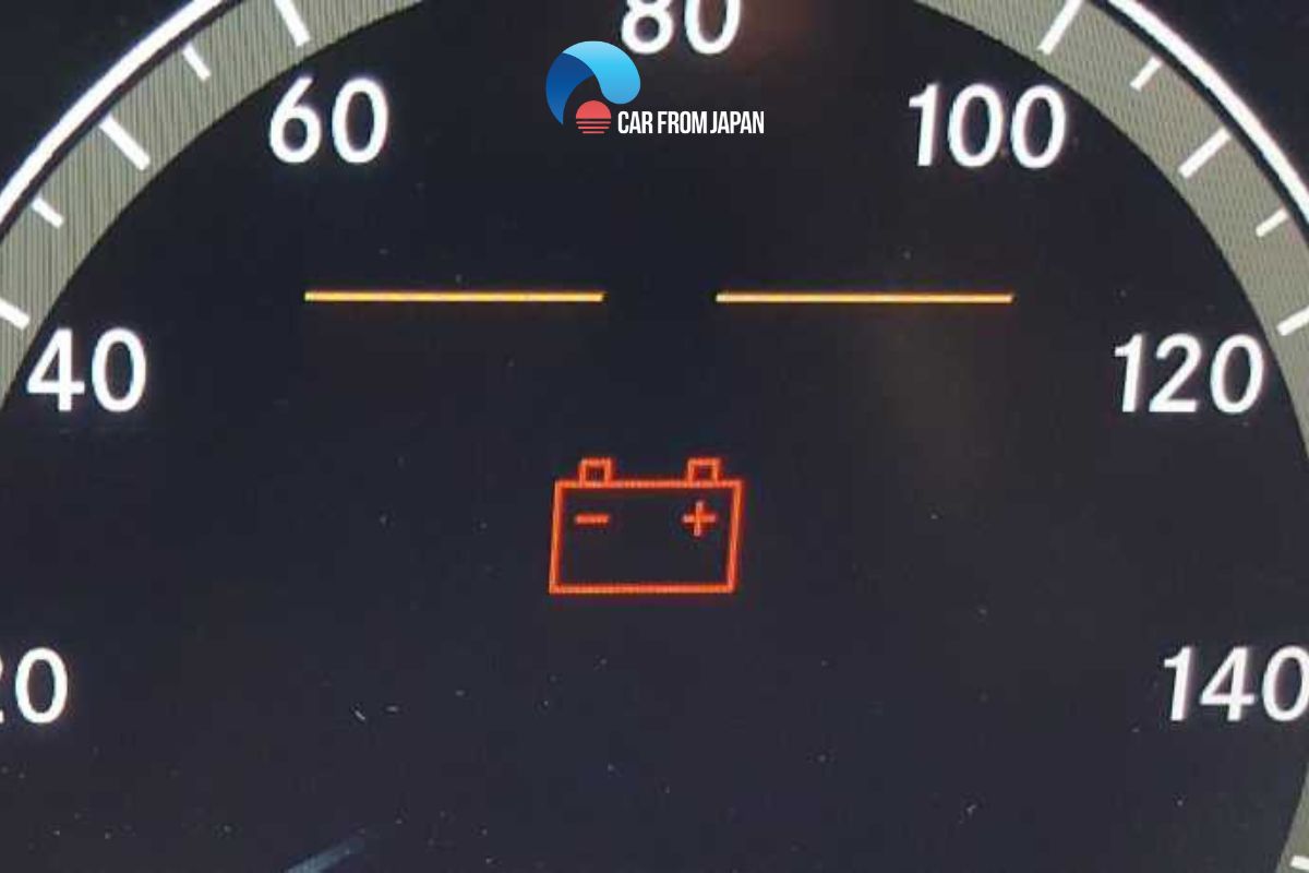
In high-tech modern vehicles, the “light” is often not a physical bulb but a digital asset rendered on a Liquid Crystal Display (LCD) or Thin-Film Transistor (TFT) instrument cluster. The Engine Control Unit (ECU) or the Body Control Module (BCM) constantly polls the alternator’s performance data via a digital signal. If the data packets indicate a charging fault, the software triggers the icon on the screen. This digital integration allows for more nuanced warnings; for instance, a vehicle might display a text-based message like “Charging System Failure” or “Check Charging System” alongside the icon, providing immediate context that an analog light could not.
Modern Diagnostic Technology and Error Codes
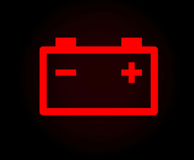
When the alternator warning light flickers to life, it marks the beginning of a digital diagnostic process. Modern technicians do not simply look at the light; they interface with the vehicle’s onboard diagnostics (OBD-II) system to extract specific error codes that pin-point the failure point within the electrical hardware.
Interpreting Diagnostic Trouble Codes (DTCs)
The light is the “user-end” notification, but the backend data provides the granular detail. Common codes associated with an alternator warning light include:
- P0562 (System Voltage Low): This indicates that the ECU has detected a voltage level consistently below the required threshold.
- P0620 (Generator Control Circuit): This points toward a communication error between the alternator and the ECU, often suggesting a wiring harness issue or a failure in the digital regulator.
- P0622 (Generator Field F Terminal): This specific code identifies an issue with the rotor circuit, helping tech-savvy users distinguish between a mechanical wear issue and an electronic failure.
Smart Alternators and Regenerative Technology
In the pursuit of fuel efficiency and reduced emissions, manufacturers have introduced “Smart Alternators.” Unlike traditional systems that charge at a constant rate, smart alternators are controlled by the ECU to vary their output based on driving conditions. During acceleration, the ECU might decouple the alternator to reduce engine load; during deceleration, it increases output to capture “free” energy, a primitive form of regenerative braking found in non-hybrid cars. The tech behind the warning light in these systems is much more sensitive, as it must distinguish between a purposeful reduction in voltage and an actual hardware malfunction.
Future Trends: The Transition to EV Monitoring Systems
As the automotive industry pivots toward electrification, the traditional alternator is being phased out. However, the concept of the alternator warning light is evolving rather than disappearing, moving into the realm of Battery Management Systems (BMS) and DC-to-DC converters.
The Disappearance of the Alternator in Electric Vehicles (EVs)
Electric vehicles do not have an alternator because they lack an internal combustion engine to drive one. Instead, they use a DC-to-DC converter to step down the high voltage from the main traction battery (often 400V or 800V) to the 12V needed for auxiliary systems like headlights and window motors. In this ecosystem, the “alternator light” is replaced by a general “electrical fault” or “12V system error” notification. The technology shifts from monitoring mechanical rotation to monitoring solid-state power conversion efficiency.
Battery Management Systems (BMS) as the New Standard
In the next generation of transport tech, the BMS is the ultimate authority. It monitors every cell’s temperature, voltage, and state of charge. If a fault occurs in the charging infrastructure—whether it’s the onboard charger or the DC converter—the warning light logic is handled entirely by complex software algorithms. This allows for predictive maintenance, where the car’s digital security and health systems can alert the driver of a potential failure weeks before the vehicle becomes undriveable, leveraging Big Data and machine learning to analyze voltage patterns.
Maintaining the Hardware: Digital and Physical Tools
For tech enthusiasts and DIY mechanics, addressing an alternator warning light involves a mix of legacy hardware testing and modern digital analysis. To accurately diagnose the system, one must bridge the gap between physical components and digital readouts.
Multimeters and Oscilloscopes
The primary tool for diagnosing the alternator’s health is the digital multimeter. By measuring the voltage at the battery terminals while the engine is running, a user can instantly verify if the alternator’s hardware is producing the required 14-volt output. For a deeper dive into the tech, an oscilloscope can be used to view the “ripple voltage.” This allows a technician to see the actual sine waves produced by the alternator; if a diode is failing, the wave will appear distorted, revealing a hardware flaw that a simple voltmeter might miss.
App-Based Telematics and OBD-II Scanners
We are currently in an era where vehicle health is accessible via smartphone. Many drivers now use Bluetooth OBD-II dongles that pair with apps to provide real-time telemetry. These tools can graph voltage fluctuations over time, allowing users to see how the charging system responds to high-drain events, such as turning on the air conditioning or the heated seats. When the alternator warning light appears, these apps provide the specific sub-codes and freeze-frame data, showing exactly what the vehicle’s sensors were detecting the moment the fault occurred. This level of transparency is a hallmark of modern automotive technology, turning a mysterious red light into a clear, actionable data point.
In conclusion, the alternator warning light is far more than a simple notification; it is the visible tip of a sophisticated technological iceberg. From the electromagnetic physics of the rotor and stator to the complex CAN bus protocols and the future of EV battery management, this icon represents the vital pulse of a vehicle’s electrical nervous system. As automotive technology continues to advance toward full electrification and software-defined architectures, the way we monitor, diagnose, and interact with our vehicle’s power systems will only become more integrated, data-driven, and precise.
aViewFromTheCave is a participant in the Amazon Services LLC Associates Program, an affiliate advertising program designed to provide a means for sites to earn advertising fees by advertising and linking to Amazon.com. Amazon, the Amazon logo, AmazonSupply, and the AmazonSupply logo are trademarks of Amazon.com, Inc. or its affiliates. As an Amazon Associate we earn affiliate commissions from qualifying purchases.