
In the intricate world of electrical engineering and physics, where invisible forces sculpt the very fabric of our technological landscape, certain fundamental concepts serve as the bedrock for innovation. Among these is “reluctance” – a term that, while perhaps not as widely recognized as “resistance” or “capacitance,” holds an equally pivotal role in the design and operation of countless electronic and electrical devices. At its core, reluctance quantifies the opposition a material or magnetic circuit presents to the establishment of magnetic flux. It is, in essence, the magnetic equivalent of electrical resistance. Understanding reluctance is not merely an academic exercise; it is essential for anyone delving into the mechanics of motors, the efficiency of transformers, the precision of sensors, or the fundamental principles governing electromagnetism.

This exploration will delve deep into the concept of magnetic reluctance, dissecting its definition, the factors that govern it, its mathematical representation, and its pervasive influence across a spectrum of technological applications. By drawing parallels with more familiar electrical concepts, we aim to demystify reluctance, revealing its critical importance in shaping the performance, efficiency, and reliability of the devices that power our modern world.
The Core Concept of Magnetic Reluctance
To truly grasp reluctance, it’s helpful to begin by understanding its fundamental nature within a magnetic circuit. Just as an electrical circuit facilitates the flow of current, a magnetic circuit guides and contains magnetic flux.
Defining Reluctance in Magnetic Circuits
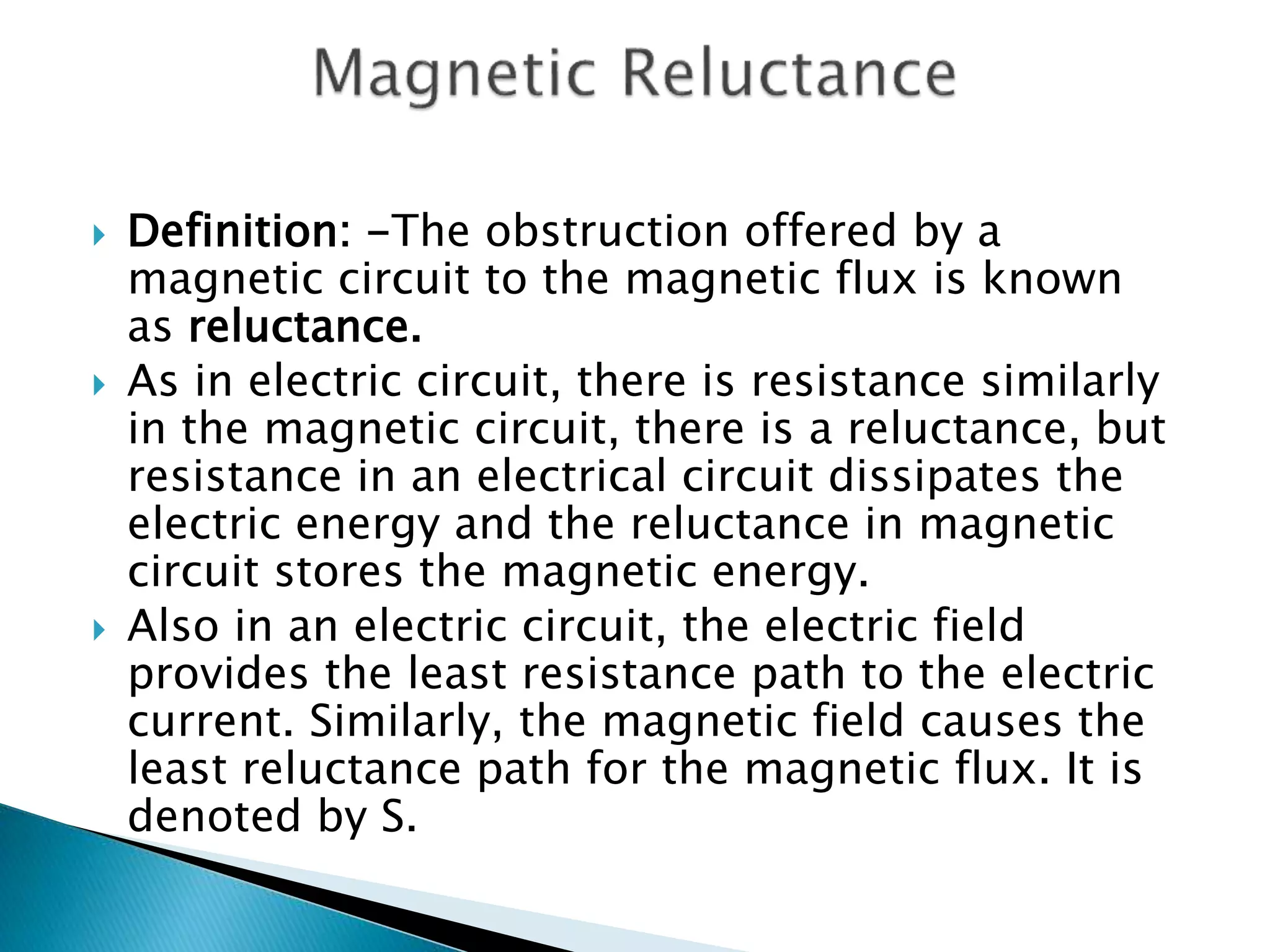
Reluctance (symbolized by R or $mathcal{R}$) is the property of a magnetic circuit that opposes the passage of magnetic flux. Imagine trying to push water through a narrow, rough pipe; the pipe offers resistance. Similarly, reluctance describes how difficult it is for magnetic field lines (magnetic flux) to pass through a given material or path. A high reluctance means it’s hard for magnetic flux to establish itself, while low reluctance implies an easy path for the flux.
The concept is often introduced through an analogy with Ohm’s Law in electrical circuits, which is sometimes referred to as the “Magnetic Ohm’s Law” or Hopkinson’s Law. In an electrical circuit:
$V = I times R_{text{electrical}}$
(Voltage = Current $times$ Electrical Resistance)
In a magnetic circuit, the analogous relationship is:
$MMF = Phi times mathcal{R}$
(Magnetomotive Force = Magnetic Flux $times$ Reluctance)
Here:
-
Magnetomotive Force (MMF) is the “driving force” that establishes magnetic flux. It’s analogous to voltage in an electrical circuit and is typically generated by a coil of wire carrying current (MMF = N $times$ I, where N is the number of turns and I is the current). Its unit is Ampere-turns (At).
-
Magnetic Flux ($Phi$) is the total number of magnetic field lines passing through a given area. It’s analogous to electrical current and is measured in Webers (Wb).
-
Reluctance ($mathcal{R}$) is the opposition to magnetic flux. Its unit is Ampere-turns per Weber (At/Wb).
From this relationship, we can derive the formula for reluctance:
$mathcal{R} = frac{MMF}{Phi}$
This formula highlights that for a given magnetomotive force, a higher reluctance will result in a lower magnetic flux, and vice versa.
Permeability: The Counterpart to Conductivity
Just as electrical conductivity describes how easily current flows through a material (the inverse of resistivity), magnetic permeability ($mu$) describes how easily a material can support the formation of a magnetic field within itself. Permeability is, therefore, inversely related to reluctance. High permeability means low reluctance, making it easier for magnetic flux to pass through.
Permeability is a crucial material property. It’s typically expressed in Henries per meter (H/m) and can be broken down into:
-
Absolute Permeability ($mu$): The total permeability of a material.
-
Permeability of Free Space ($mu_0$): A constant value (approximately $4pi times 10^{-7}$ H/m) representing the permeability of a vacuum.
-
Relative Permeability ($mur$): A dimensionless ratio indicating how much more permeable a material is compared to free space ($mu = mur times mu_0$).
The fundamental formula for reluctance, derived from these properties, is:
$mathcal{R} = frac{l}{mu A}$
Where:
-
$l$ is the length of the magnetic path (in meters).
-
$mu$ is the absolute permeability of the material (in H/m).
-
$A$ is the cross-sectional area of the magnetic path (in square meters).
This formula elegantly links the physical dimensions of a magnetic circuit with the intrinsic magnetic properties of the materials used, directly determining its reluctance.
Factors Influencing Reluctance
Understanding the formula $mathcal{R} = frac{l}{mu A}$ reveals the key factors that engineers manipulate to design magnetic circuits with specific characteristics.
Material Properties and Permeability
The choice of material is arguably the most significant factor influencing reluctance. Materials are broadly categorized based on their magnetic properties:
-
Ferromagnetic Materials: These include iron, nickel, cobalt, and their alloys. They possess very high relative permeabilities (often thousands or tens of thousands), meaning they offer very low reluctance paths for magnetic flux. These are the materials of choice for transformer cores, motor laminations, and electromagnets, where efficient channeling of magnetic flux is paramount.
-
Paramagnetic and Diamagnetic Materials: These materials have relative permeabilities close to 1 (paramagnetic, slightly greater than 1) or slightly less than 1 (diamagnetic). They offer high reluctance paths, meaning they do not significantly concentrate magnetic flux. Air is an example of a paramagnetic medium, and its permeability is effectively that of free space ($mu_0$).
A critical consideration in many magnetic circuits is the presence of air gaps. Even a small air gap in an otherwise ferromagnetic path dramatically increases the total reluctance of the circuit. This is because air has a relative permeability of 1, while the surrounding ferromagnetic material might have $mu_r > 1000$. The high reluctance of the air gap can sometimes dominate the overall reluctance, even if its physical length is small. While air gaps are often undesirable for maximizing flux, they are intentionally introduced in some devices (e.g., to prevent saturation or to create variable reluctance effects).
Geometric Dimensions
The physical shape and size of the magnetic path also play a direct and predictable role in determining reluctance:
-
Length of the Magnetic Path ($l$): Reluctance is directly proportional to the length of the path through which the magnetic flux must travel. A longer path means more material opposing the flux, thus higher reluctance. This is analogous to how a longer electrical wire has higher resistance.
-
Cross-sectional Area ($A$): Reluctance is inversely proportional to the cross-sectional area of the magnetic path. A larger area provides more “space” for the magnetic flux lines to spread out, effectively reducing the opposition, similar to how a thicker electrical wire has lower resistance.
Engineers meticulously design the geometry of magnetic cores, the thickness of laminations, and the dimensions of air gaps to achieve desired reluctance values, which in turn dictate the performance of the magnetic device.
The Significance and Applications of Reluctance in Technology
Reluctance is not just a theoretical concept; it is a fundamental design parameter that engineers actively manage in a vast array of technologies. Its manipulation allows for the control and harnessing of magnetic fields, leading to the sophisticated devices we rely on daily.
Electric Motors and Generators
In the heart of almost every electric motor and generator lies the principle of reluctance.
-
Switched Reluctance Motors (SRMs): These motors explicitly exploit the variation of reluctance to produce torque. The rotor is designed with salient poles, and as it rotates, the reluctance path between the stator poles and rotor poles changes. The motor control system energizes stator windings in sequence, creating a magnetic field that pulls the rotor into a position of minimum reluctance, thus generating motion. SRMs offer robust construction, fault tolerance, and efficiency over a wide speed range.
-
Variable Reluctance Generators: Similar to motors, these generators convert mechanical energy into electrical energy by varying the magnetic reluctance in their magnetic circuit as the rotor spins, inducing a current in the stator windings.
-
General Motor Design: In all types of motors, the design of the stator and rotor cores involves minimizing reluctance in desired flux paths to maximize magnetic force and efficiency, while strategically managing leakage flux which represents flux that does not contribute to torque production.
Transformers
Transformers, critical for stepping up or stepping down AC voltage, are prime examples of reluctance management.
-
Minimizing Core Reluctance: The core of a transformer is typically made of laminated ferromagnetic material (e.g., silicon steel) chosen for its very high permeability and low reluctance. This low reluctance path ensures that almost all the magnetic flux generated by the primary coil links effectively with the secondary coil, maximizing energy transfer efficiency.
-
Leakage Flux: While ideally all flux would be contained within the core, some flux inevitably “leaks” into the surrounding air, failing to link both coils. This leakage flux, which represents magnetic energy stored in a high-reluctance air path, is an imperfection that reduces transformer efficiency and voltage regulation. Designers aim to minimize leakage reluctance through careful winding placement and core geometry.
Inductors and Electromagnets
Reluctance is central to the design and function of inductors and electromagnets.
-
Inductors: An inductor is essentially a coil of wire designed to store energy in a magnetic field. The inductance value (L) is directly related to the reluctance of the magnetic path. By adding a high-permeability, low-reluctance core (e.g., ferrite or iron) to an air-core coil, engineers can dramatically increase its inductance for a given number of turns, enabling more compact and powerful energy storage.
-
Electromagnets: The strength of an electromagnet (the force it exerts) depends on the magnetic flux it can generate. To maximize this flux for a given MMF (current and turns), the electromagnet’s core is designed with very low reluctance. Conversely, in applications requiring variable magnetic force, the reluctance can be intentionally varied (e.g., by changing an air gap) to control the electromagnet’s strength.
Magnetic Sensors and Data Storage
Reluctance also plays a role in various sensing and storage technologies.
-
Variable Reluctance Sensors: These sensors detect changes in position, speed, or presence by sensing variations in magnetic reluctance. For example, a toothed wheel passing by a stationary coil induces a voltage change due to the fluctuating reluctance of the magnetic path, allowing for precise speed measurement in automotive applications.
-
Early Magnetic Recording: In older hard drives and tape drives, the read/write heads interacted with magnetic media by creating and sensing magnetic fields. The design of these heads involved managing reluctance to focus the magnetic flux precisely for writing data and to efficiently pick up faint magnetic flux changes for reading data.
Designing with Reluctance: Engineering Challenges and Solutions
The practical application of reluctance in technology often involves complex trade-offs and sophisticated engineering solutions.
Minimizing Core Losses
While low reluctance ferromagnetic materials are ideal for channeling flux, they are also susceptible to energy losses when exposed to changing magnetic fields.
-
Hysteresis Losses: Energy is lost as heat when the magnetic domains in a material repeatedly reorient themselves with a changing magnetic field. Materials with narrow hysteresis loops are preferred, indicating lower energy loss.
-
Eddy Current Losses: Changing magnetic flux can induce circulating currents (eddy currents) within the conductive core material, leading to resistive heating. To combat this, transformer and motor cores are made of thin laminations of steel, separated by insulating layers. This increases the reluctance path for eddy currents, effectively minimizing their magnitude and associated losses, while maintaining a low reluctance path for the main magnetic flux.
Optimizing Magnetic Circuits
Designing an optimal magnetic circuit is a multi-objective problem:
-
Balancing Flux Paths: Engineers use finite element analysis (FEA) software to model and simulate magnetic field distribution, ensuring that flux is channeled efficiently where needed and leakage flux is minimized.
-
Material Selection: Choosing the right ferromagnetic material involves considering its permeability, saturation flux density (the maximum flux a material can carry before its reluctance dramatically increases), and core loss characteristics.
-
Air Gaps: While often a source of high reluctance, controlled air gaps are sometimes necessary to prevent core saturation, to linearize an inductor’s behavior, or to create the variable reluctance effects exploited in motors and sensors. The challenge is to design air gaps precisely.
Variable Reluctance Technology
Modern power electronics and control systems have unlocked new potential for variable reluctance technology. Advanced control algorithms allow for precise management of current pulses to create highly efficient and robust switched reluctance motors. These motors are gaining traction in applications where high torque density, wide speed range, and harsh environment operation are critical, such as electric vehicles and industrial drives. The ongoing research into advanced magnetic materials and manufacturing techniques continues to push the boundaries of what’s possible with reluctance-based devices.

Conclusion
Reluctance, the magnetic equivalent of electrical resistance, stands as a cornerstone concept in electrical engineering and the broader field of technology. From the fundamental principles governing how a simple electromagnet lifts metal to the intricate dance of magnetic fields within a high-performance electric motor, an understanding of reluctance is indispensable. It dictates the efficiency of transformers, the precision of sensors, and the very viability of energy conversion devices.
By carefully selecting materials with appropriate permeability, meticulously designing the geometry of magnetic circuits, and strategically incorporating (or avoiding) air gaps, engineers harness and manipulate reluctance to achieve desired performance characteristics. The ongoing evolution of magnetic materials, sophisticated modeling tools, and advanced control systems continues to expand the horizons of reluctance-based technologies, promising even more efficient, powerful, and compact devices in the future. As technology advances, the seemingly abstract concept of reluctance remains a profoundly practical and vital tool in the engineer’s toolkit, silently powering the innovations that define our modern world.
aViewFromTheCave is a participant in the Amazon Services LLC Associates Program, an affiliate advertising program designed to provide a means for sites to earn advertising fees by advertising and linking to Amazon.com. Amazon, the Amazon logo, AmazonSupply, and the AmazonSupply logo are trademarks of Amazon.com, Inc. or its affiliates. As an Amazon Associate we earn affiliate commissions from qualifying purchases.