
The evolution of Light Emitting Diode (LED) technology has moved at a blistering pace over the last decade, transitioning from simple indicator lights on electronic devices to the primary source of illumination for our cities, homes, and specialized hardware. Among the most significant advancements in this field is Chip on Board (COB) technology. While many consumers are familiar with the bright, energy-efficient nature of standard LEDs, COB represents a fundamental shift in how semiconductors are packaged and utilized to produce light. This technology is not merely an incremental upgrade; it is a re-engineering of the LED architecture that prioritizes lumen density, thermal efficiency, and light quality.
The Anatomy of COB: Beyond the Traditional LED
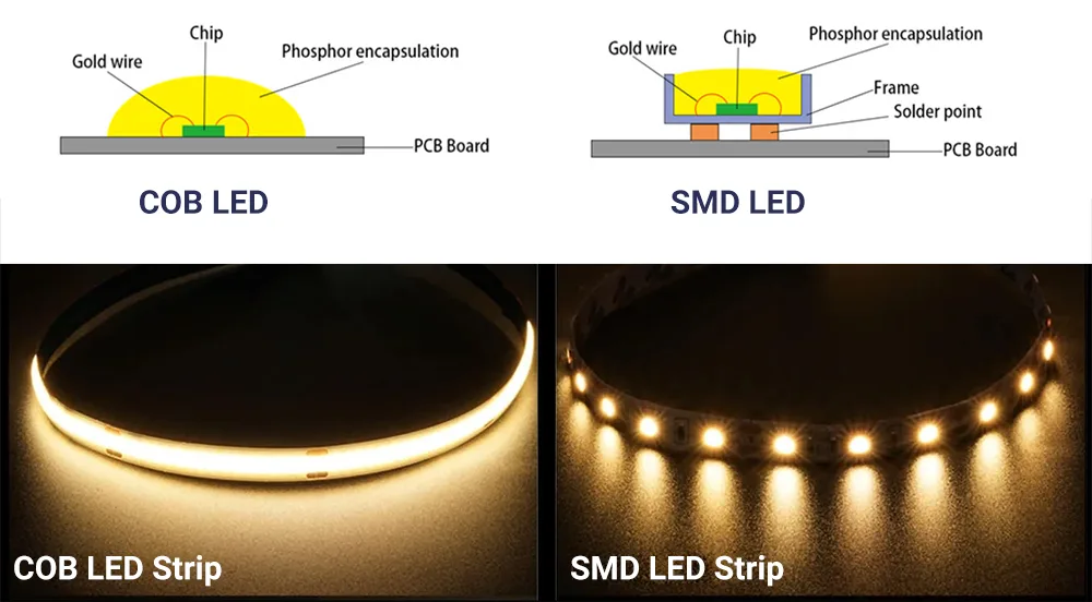
To understand what Chip on Board LED is, one must first understand how it differs from its predecessors. For years, the industry standard was the Surface Mounted Device (SMD) LED. In an SMD setup, individual LED chips are placed in a protective housing and then mounted onto a circuit board. While effective, this creates a “multi-point” light source where each individual diode is visible, often resulting in a “spotted” or “pixelated” light effect.
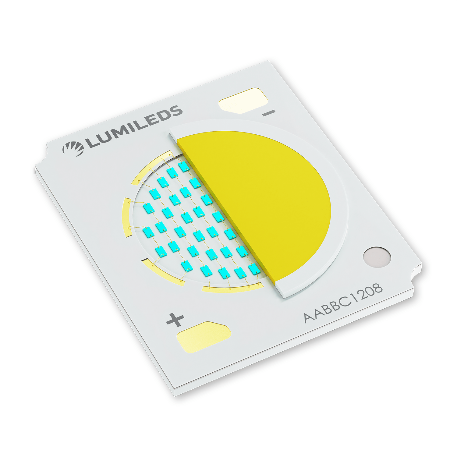
COB technology strips away these individual housings. In a COB LED, multiple LED chips (typically nine or more) are bonded directly to a substrate, such as silicon carbide, aluminum, or ceramic. This substrate acts as a single, unified circuit board. Because the individual diodes are not packaged separately, they can be placed much closer together than in any other LED configuration. Once the chips are bonded, they are covered with a single layer of phosphor epoxy, creating a single, uniform light-emitting surface.
The Manufacturing Process: Precision at the Micro Scale
The creation of a COB LED involves several high-precision engineering steps. It begins with “die-bonding,” where the bare LED chips are attached to the substrate using thermally conductive adhesives or solder. Following this, “wire-bonding” connects the electrical contacts of the chips to the circuit on the substrate. The final and perhaps most critical step is “encapsulation.” A phosphor-infused resin is applied over the entire array. This resin serves two purposes: it protects the delicate internal wiring and converts the raw blue light emitted by the chips into the broad-spectrum white light we use for illumination.
Substrate Materials and Thermal Conductivity
The choice of substrate is a critical technical decision in COB design. Because COB arrays pack many chips into a tiny area, they generate significant heat. Engineering the substrate to manage this heat is paramount. Aluminum is frequently used for its cost-effectiveness and decent thermal properties, but high-performance COB LEDs often utilize ceramic substrates (like Alumina or Aluminum Nitride). These materials offer superior thermal conductivity and electrical insulation, allowing the COB to operate at higher wattages without the risk of thermal runaway or premature degradation of the semiconductor material.
Unpacking the Technical Advantages of COB LEDs
The shift toward COB technology in high-end gadgets, professional photography gear, and industrial lighting is driven by several distinct technical advantages. By condensing the light source into a single module, engineers have solved many of the limitations inherent in traditional LED arrays.
Unparalleled Lumen Density
Lumen density refers to the amount of light emitted per square inch of the light source. Because COB LEDs eliminate the bulky packaging of individual diodes, they can achieve a much higher lumen output within a compact footprint. For example, a COB LED measuring just 10mm by 10mm can produce as much light as a much larger array of SMD LEDs. This makes COB the gold standard for applications where space is at a premium but high intensity is required, such as in smartphone camera flashes or compact tactical flashlights.
Superior Thermal Management
In the world of electronics, heat is the enemy of longevity. Standard LEDs often struggle with heat because the thermal energy must pass through multiple layers—the chip, the plastic housing, the solder, and finally the PCB—before it can be dissipated. In a COB configuration, the chips are in direct contact with the substrate. This streamlined thermal path allows heat to move away from the light-producing junction much more efficiently. Improved cooling not only extends the lifespan of the LED to 50,000 hours or more but also ensures that the color temperature remains stable over time.
Exceptional Light Uniformity and Beam Control
One of the most praised aspects of COB technology is the quality of the light it produces. Because it functions as a single “panel” of light rather than a collection of points, it produces a smooth, uniform beam. This eliminates the “multi-shadow” effect that occurs when multiple SMD chips cast overlapping shadows. For tech enthusiasts and professionals in the film and photography industries, this uniformity is essential. Furthermore, because the light source is so small and concentrated, it is much easier to focus using reflectors or lenses, allowing for tighter beam angles and more precise optical control.
Practical Applications in the Modern Tech Landscape
As COB technology has matured, it has found its way into a diverse array of high-tech applications, often replacing older HID (High-Intensity Discharge) and halogen systems that were previously thought to be irreplaceable.
High-End Photography and Cinematography
Professional lighting for film and photography has been revolutionized by COB LEDs. Manufacturers like Aputure and Godox utilize large COB arrays to create “point-source” lights that can mimic the intensity of a traditional 1200W HMI lamp while drawing significantly less power and producing almost no heat. These lights often feature high Color Rendering Index (CRI) and Television Lighting Consistency Index (TLCI) ratings, ensuring that skin tones and colors are reproduced accurately on digital sensors.
Industrial and Architectural Lighting
In industrial settings, such as warehouses or stadiums, high-bay lighting requires massive amounts of light from a single fixture. COB LEDs are ideal here because they can be driven at high wattages while maintaining a compact form factor. In architectural lighting, the “clean” look of a COB strip—which looks like a continuous line of light rather than a series of dots—is highly sought after for under-cabinet lighting, cove lighting, and accentuating modern geometric designs.
Consumer Electronics and Smartphones
If you look at the flash on a modern flagship smartphone, you are likely looking at a COB LED. Manufacturers need a light source that is incredibly thin, powerful enough to illuminate a dark room, and efficient enough not to drain the battery. COB technology provides the only viable solution that meets all three criteria. Additionally, as electric vehicles (EVs) become more sophisticated, COB LEDs are being integrated into headlight assemblies to provide high-performance adaptive beam patterns that can “steer” light around corners.
COB vs. SMD: Making the Right Technical Choice
While COB is superior in many ways, it has not rendered SMD technology obsolete. Understanding the trade-offs between the two is essential for hardware designers and tech-savvy consumers alike.
The primary limitation of COB LED technology is its lack of versatility in color mixing. Because all the chips in a COB array are covered by a single phosphor coating, it is difficult to create a “true” RGB COB that can change colors as fluidly as an SMD array. In an SMD strip, each diode can contain a Red, Green, and Blue chip that can be controlled independently. This makes SMD the preferred choice for smart lighting, gaming setups (RGB peripherals), and digital signage where color dynamics are the priority.
However, when the goal is “white light” performance—meaning brightness, efficiency, and light quality—COB wins every time. COB LEDs are also generally more efficient in terms of lumens-per-watt because they require fewer internal circuits and suffer from less light interference within the package. For a dedicated work light, a high-performance flashlight, or an architectural spotlight, the concentrated power of a COB array is unmatched.
Engineering Challenges and the Path Forward
Despite its current dominance, COB technology continues to evolve as engineers tackle its remaining hurdles. One of the primary challenges is the “yellow patch” effect. Because of the way phosphor is applied, some lower-quality COB lights can show a slight yellow tint at the edges of the beam. Solving this requires advanced deposition techniques to ensure the phosphor layer is perfectly uniform at a microscopic level.
We are also seeing the emergence of “Flip-Chip” COB technology. In traditional COB, wires connect the top of the chip to the substrate. Flip-chip technology removes these wires entirely by flipping the chip over and bonding the contacts directly to the board. This reduces the risk of wire failure, further improves heat dissipation, and allows for even denser chip configurations.
The future of solid-state lighting likely lies in the further miniaturization of this concept, moving toward Micro-LED and Mini-LED technologies. However, for the foreseeable future, Chip on Board remains the pinnacle of high-intensity, high-efficiency lighting. It represents a perfect marriage of semiconductor physics and thermal engineering, providing the high-quality illumination required by the next generation of professional and consumer technology. Whether it is in the studio, on the street, or in the palm of your hand, COB LEDs are the invisible engine driving the modern visual experience.
aViewFromTheCave is a participant in the Amazon Services LLC Associates Program, an affiliate advertising program designed to provide a means for sites to earn advertising fees by advertising and linking to Amazon.com. Amazon, the Amazon logo, AmazonSupply, and the AmazonSupply logo are trademarks of Amazon.com, Inc. or its affiliates. As an Amazon Associate we earn affiliate commissions from qualifying purchases.