
The Fundamental Mechanism
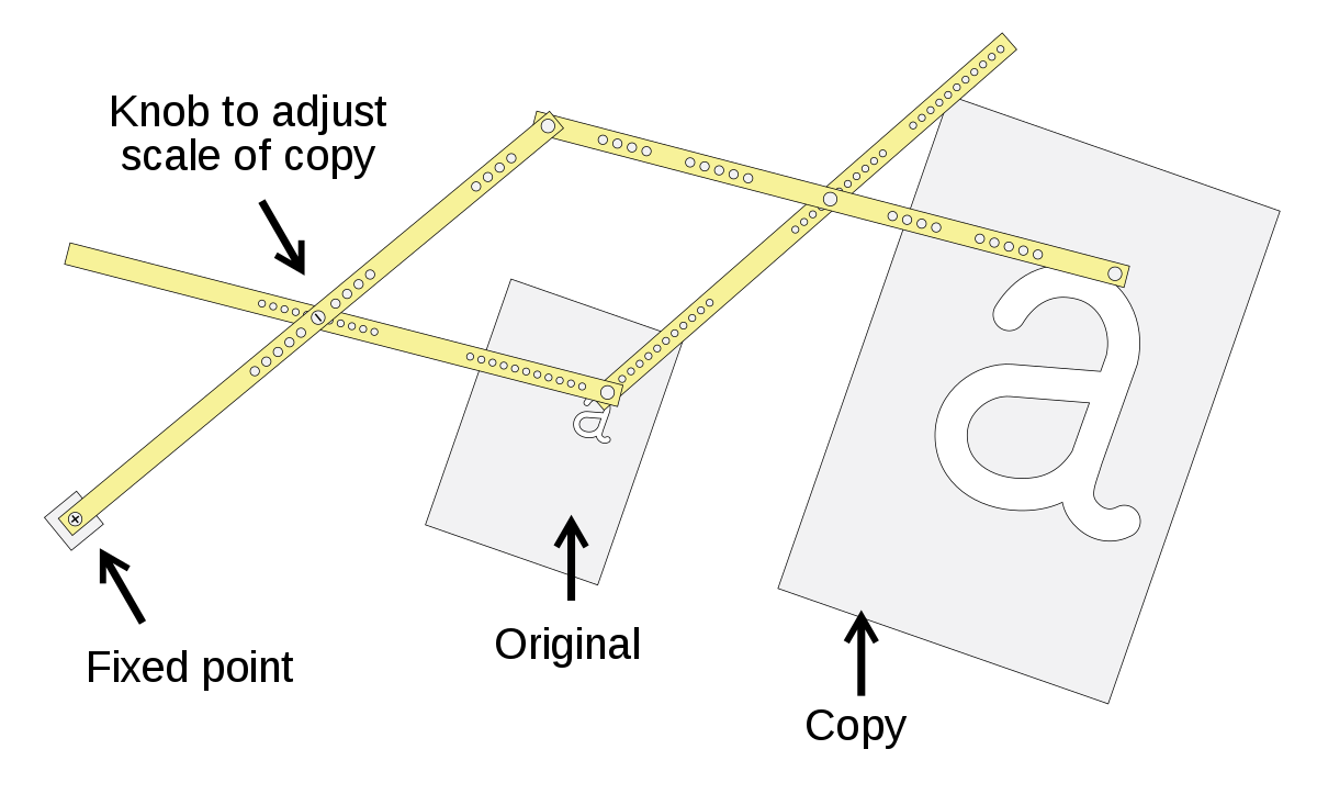
A pantograph is an ingenious mechanical linkage connected in a manner based on parallelograms, allowing a tracer point to copy a drawing or design at an adjusted scale. Its core principle relies on geometric similitude, making it a powerful tool for scaling and replication without the need for complex mathematical calculations during operation. The term “pantograph” itself derives from the Greek words “panta” (all, every) and “grapho” (to write), aptly describing its universal copying ability. At its heart, it is a device that translates motion proportionally, a concept that has found diverse applications across various technological domains.
Geometric Principles at Play
The magic of a pantograph lies in its simple yet profound geometric foundation. It consists of several interconnected rods, typically hinged to form a series of parallelograms. One point on this linkage is fixed, acting as a pivot. Another point, the tracer, follows the original drawing, while a third point, the pencil or stylus, replicates the drawing at a different scale. The critical aspect is that the fixed pivot, the tracer point, and the copying point always remain collinear. This collinearity, maintained by the parallelogram structure, ensures that the ratio of distances from the pivot to the tracer and from the pivot to the copying point remains constant. This constant ratio is the scaling factor. If the copying point is further from the pivot than the tracer, the drawing is enlarged; if it’s closer, it’s reduced. The angles and proportions are faithfully preserved, making it an affine transformation tool. This elegant mechanical solution leverages basic Euclidean geometry to perform a complex task with remarkable simplicity and precision.
Components of a Basic Pantograph
A typical drawing pantograph, for instance, comprises four main bars, usually made of wood, plastic, or metal, joined by pivot pins.
- Fixed Pivot: This is the anchor point that remains stationary during operation. It determines the center of scaling and provides the stable base for the entire mechanism.
- Tracer Arm: One end of this arm carries the tracer point, which is carefully guided along the lines of the original artwork or design. This arm’s movement dictates the input.
- Copying Arm: This arm holds the stylus or pen that draws the scaled copy. The position of this arm relative to the tracer arm and fixed pivot determines the specific scaling ratio being applied.
- Connecting Rods: These rods complete the parallelogram linkage, ensuring the parallel movement and constant ratio between the tracer and copying points. Their precise lengths and connections are crucial for the pantograph’s accurate operation.
The precise placement of the pivot points along the arms is crucial for setting the desired scaling factor, which is often adjustable through marked holes or sliding mechanisms on the arms themselves. This adjustability allows for versatility in scaling from small reductions to significant enlargements.
Diverse Applications Across Industries
While often associated with antique drafting tools, the pantograph’s underlying principle has found remarkably diverse and enduring applications across numerous technological fields, evolving from a simple drawing aid to a critical component in complex machinery. Its ability to translate motion and maintain proportionality has proven invaluable in contexts far removed from its original purpose.
Engineering and Drafting
Historically, the pantograph was an indispensable tool for engineers, architects, and cartographers. Before the advent of CAD software and large-format printers, scaling drawings up or down accurately was a laborious task. A mechanical pantograph allowed precise reproduction of plans, maps, and blueprints, saving countless hours and ensuring dimensional accuracy. From detailed mechanical parts to vast geographical maps, the pantograph provided a reliable method for visual scaling and reproduction in technical drawing offices worldwide. Its introduction significantly streamlined the design and documentation process, making complex projects more manageable.
Manufacturing and Engraving
In manufacturing, the pantograph’s ability to precisely replicate movement at a different scale found a natural home in engraving machines. Pantograph engravers, common in the mid-20th century, used a large template to guide the tracer, while a smaller cutting tool would etch the design onto a workpiece, such as metal plates, plastic labels, or jewelry. This allowed for the rapid and accurate production of multiple identical parts or inscriptions, from intricate watch faces to industrial nameplates, long before CNC (Computer Numerical Control) machines became widespread. The same principle was also adapted for routing and carving larger objects, demonstrating its versatility in material removal processes where precise duplication was key.
Railway and Electrical Systems

One of the most visible and critical modern applications of the pantograph is in electric rail transport. Here, the device isn’t for scaling drawings but for maintaining consistent electrical contact. An electric locomotive pantograph is an articulated framework mounted on the roof, designed to collect current from overhead lines (catenary). The mechanical linkage ensures that the contact shoe at the top maintains constant pressure and contact with the catenary wire, even as the train moves and the height of the wire fluctuates due to track undulations or changes in overhead structure. This robust, flexible connection is vital for continuous power supply to the train’s motors and auxiliary systems, enabling modern electric rail travel across vast networks. Variants are also used in trolleybuses and other electric vehicles that draw power from overhead lines.
Artistic and Educational Uses
Beyond its technical prowess, the pantograph has also been embraced in artistic and educational contexts. Artists use it for scaling sketches or transferring designs to different surfaces with precise proportionality. In educational settings, it serves as an excellent pedagogical tool for demonstrating geometric principles, particularly similarity and proportion, and for introducing students to basic mechanical linkages and their practical applications. Many toy versions exist, allowing children to experiment with scaling and drawing, fostering an early understanding of these fundamental concepts in engineering and design.
Evolution and Modern Interpretations
While the fundamental geometric principle remains constant, the pantograph concept has evolved significantly, adapting to new technologies and finding niche applications in the digital age. Its core idea of proportional transformation has been abstracted and integrated into more complex systems.
From Mechanical to Digital
The rise of computer-aided design (CAD) software and advanced digital printing technologies has largely superseded the mechanical drawing pantograph for tasks like scaling blueprints. However, the underlying concept of transforming motion or coordinates at a fixed ratio persists. Digital “pantographs” can be thought of conceptually within CAD programs, where scaling operations are performed algorithmically rather than mechanically. Moreover, the input devices for CAD, like digitizer tablets, can be seen as digital descendants, translating physical pen movements into scaled digital coordinates. Some advanced 3D scanners and measuring arms incorporate pantograph-like kinematics for precise positional tracking, demonstrating how the principle endures even when the physical form changes.
Specialized Industrial Pantographs
In industrial automation and robotics, sophisticated pantograph-like mechanisms are employed for tasks requiring precise, repeatable motion over a defined workspace. These might include robotic arms designed with parallelogram linkages to maintain a specific tool orientation or to provide high stiffness and accuracy in certain degrees of freedom. For instance, some parallel kinematic machines (PKM) or delta robots leverage similar principles to achieve rapid and precise movements of an end-effector, albeit in a more complex, multi-axis configuration. These modern industrial pantographs prioritize speed, rigidity, and computational control over simple manual scaling, showcasing the adaptability of the core concept to high-tech manufacturing challenges.
Advantages and Limitations
Like any technology, the pantograph offers distinct advantages for specific applications but also comes with inherent limitations that have driven its evolution and the adoption of alternative solutions. Understanding these trade-offs is crucial to appreciating its place in technological history and its continued relevance.
Precision and Scalability
The primary advantage of a mechanical pantograph is its ability to perform precise scaling operations quickly and without complex calculations. For drafting and engraving, it provided an elegant solution for replicating designs at various sizes while maintaining geometric fidelity. The inherent mechanical rigidity, especially in well-constructed models, ensured high accuracy for its intended purpose. In electrical systems, its advantage lies in its robust yet flexible mechanical compliance, allowing it to adapt to varying overhead wire heights and maintain continuous electrical contact reliably under dynamic conditions. This self-adjusting mechanism is a testament to its practical engineering design, providing a passive yet effective solution for power collection.

Physical Constraints and Alternatives
Despite its benefits, the mechanical pantograph has several limitations. It’s fundamentally a planar device, meaning it typically works in two dimensions, though more complex 3D versions exist for specific applications like sculpture duplication. The size of the original and the copy is constrained by the physical length of the arms. Accuracy can be affected by wear in the pivot points over time, leading to ‘slop’ or play, and by the manual skill of the operator for drawing applications. For tasks requiring extreme precision, very large-scale changes, or three-dimensional manipulation, other technologies have often proven superior. CNC machines, laser cutters, and advanced robotics have largely replaced pantograph engravers for mass production, offering greater automation, precision, and versatility in material processing and multi-axis operations. Similarly, digital design and printing have superseded manual drafting pantographs. However, the core principle of proportional linkage remains an elegant solution for specific engineering challenges, particularly where mechanical simplicity and robust, passive compliance are paramount, as seen in railway applications. The pantograph stands as a foundational example of how simple mechanical principles can be leveraged to create enduring and impactful technological solutions.
aViewFromTheCave is a participant in the Amazon Services LLC Associates Program, an affiliate advertising program designed to provide a means for sites to earn advertising fees by advertising and linking to Amazon.com. Amazon, the Amazon logo, AmazonSupply, and the AmazonSupply logo are trademarks of Amazon.com, Inc. or its affiliates. As an Amazon Associate we earn affiliate commissions from qualifying purchases.