
In the intricate world of modern heating systems and gas appliances, safety and efficiency are paramount. At the heart of these critical functions lies a small, often overlooked component: the flame sensor. This unassuming part is a silent guardian, diligently ensuring that gas flows only when a flame is present, preventing hazardous gas buildups and ensuring your system operates as intended. However, like any component under constant stress, flame sensors can degrade and fail. Understanding the signs of a bad flame sensor isn’t just about troubleshooting; it’s about maintaining safety, preventing costly repairs, and ensuring consistent comfort in your home or operational efficiency in your industrial settings.
This article delves into the appearance and behavior of a faulty flame sensor, equipping you with the knowledge to identify problems early, perform basic diagnostics, and know when to call in the professionals. From erratic cycling to complete system shutdowns, we’ll explore the telltale indicators that signal your flame sensor might be failing, all while maintaining a sharp focus on the underlying technology and its practical implications.
The Unseen Guardian: Understanding the Flame Sensor’s Role
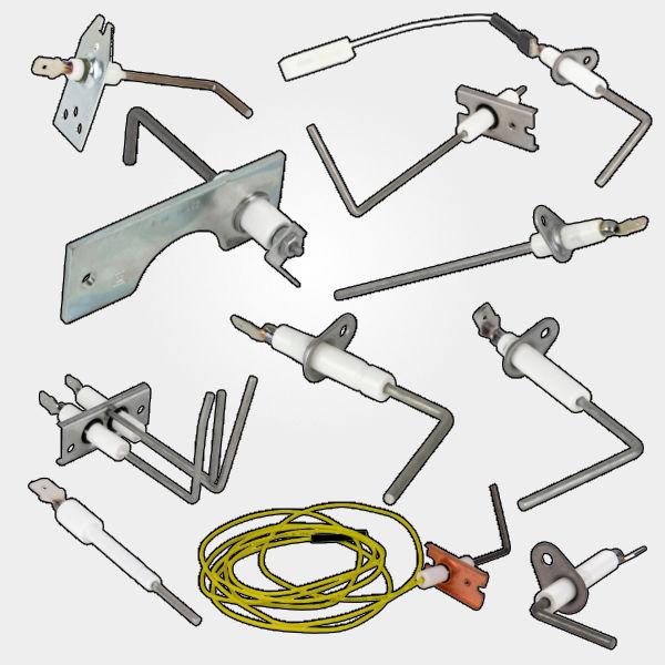
Before we can identify a problem, it’s crucial to understand the normal function of a flame sensor. Often a simple rod-like electrode, typically made of Kanthal (an iron-chromium-aluminum alloy), encased in a ceramic insulator, the flame sensor plays a critical, life-saving role in any gas-fired appliance, from furnaces and boilers to water heaters and commercial ovens.
How a Flame Sensor Works
The principle behind a flame sensor is elegantly simple yet ingeniously effective. When a gas appliance ignites, the flame itself becomes electrically conductive due to the ionization of gas molecules at high temperatures. The flame sensor works by exploiting this phenomenon through a process called “flame rectification.”
Here’s a simplified breakdown:
-
Voltage Application: A small alternating current (AC) voltage is applied to the flame sensor rod, typically by the appliance’s control board.
-
Current Flow through Flame: When a stable flame envelops the sensor rod, the ionized gases within the flame allow a tiny electrical current (measured in microamperes, or µA) to flow from the flame sensor rod, through the flame, and back to a grounded component of the burner assembly. Because the flame offers less resistance in one direction (from the larger grounded surface to the smaller sensor rod), the AC signal is rectified into a pulsating direct current (DC) signal.
-
Signal Interpretation: The appliance’s control board constantly monitors this minute DC current. If the current is detected within a specific range (typically between 1 to 5 microamperes), the control board confirms the presence of a stable flame.
-
Safety Interlock: Upon confirming the flame, the control board keeps the gas valve open, allowing the burners to continue operating. If, however, the current drops below the threshold or is absent, the control board interprets this as a “no flame” condition. In response, it immediately closes the gas valve, shutting off the gas supply to prevent uncombusted gas from accumulating, which could lead to an explosion. This entire process happens within mere seconds of ignition.
This rapid response mechanism is the cornerstone of safety in gas appliances, preventing dangerous gas leaks and ensuring only safe, controlled combustion occurs.
Why Flame Sensors Go Bad
Despite their robust construction, flame sensors operate in an extremely harsh environment. Their constant exposure to high temperatures, combustion byproducts, and electrical stress makes them susceptible to various forms of degradation.
Common reasons why flame sensors fail include:
-
Soot and Carbon Buildup: This is arguably the most common culprit. As natural gas burns, it can produce tiny amounts of carbon and other particulates. These deposits accumulate on the surface of the flame sensor rod, acting as an insulator. This layer of soot obstructs the electrical conductivity of the flame, preventing the microampere current from flowing effectively. The control board then falsely interprets this as an absence of flame.
-
Corrosion and Oxidation: Over time, the metallic rod can corrode or oxidize, especially in environments with high humidity or exposure to certain chemicals. This surface degradation increases electrical resistance, impeding current flow.
-
Cracked or Damaged Ceramic Insulator: The ceramic base that supports the metallic rod is crucial for isolating the electrical signal. Physical impact, thermal shock (rapid heating and cooling), or prolonged stress can cause cracks in the ceramic. A compromised insulator can lead to ground faults or improper signal transmission.
-
Wear and Tear: Constant thermal cycling and exposure to intense heat can degrade the integrity of the metal rod itself, making it less conductive or causing it to become brittle.
-
Loose or Corroded Wiring: While not strictly a flame sensor fault, poor electrical connections between the sensor and the control board can mimic a bad flame sensor. Corroded terminals or loose wires prevent the microamp signal from reaching the control board.
-
Bending or Misalignment: The flame sensor must be positioned correctly within the flame path to work effectively. If the rod gets accidentally bent or jostled out of position, it may not be sufficiently immersed in the flame, leading to intermittent or no signal detection.
Understanding these failure modes is the first step in recognizing the symptoms of a problematic flame sensor.
Telltale Signs of a Failing Flame Sensor
When a flame sensor begins to fail, its inability to accurately report the presence of a flame triggers safety mechanisms that directly impact the appliance’s operation. These symptoms are often distinct and can provide clear clues that the flame sensor is the root cause of the issue.
The Appliance Cycles On and Off Rapidly (Short Cycling)
This is perhaps the most common and frustrating symptom of a bad flame sensor in a furnace or similar heating system.
-
Description: You’ll notice the appliance (e.g., furnace) attempting to ignite. The igniter glows, the gas valve opens, the burners light up, and you see a flame. However, within a few seconds (typically 3-7 seconds), the burners abruptly shut off. After a brief pause, the system attempts to ignite again, repeating the cycle multiple times.
-
Explanation: This short cycling is a direct consequence of the flame sensor failing to detect the flame it’s exposed to. The control board initiates ignition, sees the igniter glow, and opens the gas valve. The burners light successfully. But because the dirty, corroded, or damaged flame sensor isn’t sending the required microamp signal back to the control board, the board assumes there’s no flame and immediately closes the gas valve as a safety measure. The system then enters a purge cycle and tries again, often with the same result, until it eventually locks out.
No Heat or Intermittent Heat
While short cycling delivers some heat, a more severe flame sensor issue can result in a complete lack of heat or highly unreliable heating.
-
Description: The furnace might try to start, but the main burners never consistently stay lit, or they don’t light at all after the igniter glows. In water heaters or ovens, the burner may fail to stay on, leading to cold water or undercooked food.
-
Explanation: If the flame sensor is severely compromised, it might not register a flame even during the first ignition attempt, leading to an immediate shutdown and preventing any sustained heating. Intermittent issues can arise from marginal sensor performance, where it sometimes detects the flame and sometimes doesn’t.
Error Codes on the Control Board
Modern gas appliances are equipped with sophisticated diagnostic systems that can often pinpoint the exact nature of a fault.
-
Description: Most furnaces and many other gas appliances have a control board with an LED light that flashes in a specific pattern when an error occurs. You might find a chart on the inside of the furnace access panel that correlates these flash codes to specific problems.
-
Explanation: A common error code associated with a faulty flame sensor is often labeled “Ignition Lockout,” “No Flame Detected,” or “Failed to Ignite.” These codes indicate that the control board made multiple attempts to establish a flame and failed, frequently due to the flame sensor not providing a confirmation signal. Consulting your appliance’s manual for these flash codes is an excellent way to narrow down the problem.
System Lockout and Safety Shutdowns

When repeated attempts to ignite fail due to a bad flame sensor, the appliance’s safety mechanisms kick in to prevent potentially dangerous situations.
-
Description: After several failed ignition attempts (usually three to five, depending on the manufacturer), the control board will initiate a “hard lockout.” This means the system will completely shut down and will not attempt to ignite again until the power is cycled (turned off and then back on) or a specific reset procedure is followed.
-
Explanation: This lockout is a critical safety feature designed to prevent raw gas from accumulating in the combustion chamber or flue if the ignition system repeatedly fails. It’s the ultimate consequence of a flame sensor failing to confirm flame presence. While frustrating, it’s a sign that the safety system is working to protect you.
It’s important to remember that while these symptoms strongly suggest a flame sensor issue, other components of the ignition system (e.g., igniter, gas valve, control board) can sometimes present similar symptoms. Therefore, further diagnosis is often required.
Diagnosing a Faulty Flame Sensor: A DIYer’s Guide (with Caution)
Before calling a professional, many homeowners and technicians can perform basic checks and maintenance on a flame sensor. These steps can often resolve common issues, but always prioritize safety, especially when working with gas appliances.
Visual Inspection
The first step is always to locate and visually inspect the flame sensor.
-
Location: In most furnaces, the flame sensor is a thin metal rod, usually 2-3 inches long, with a single wire attached to its ceramic base. It’s typically located on the opposite side of the burner assembly from the igniter, positioned directly in the path of the flame. You’ll usually need to remove the front access panel of the furnace to gain access.
-
What to Look For:
-
Soot and Carbon Buildup: This will appear as a dull, black, or flaky residue coating the metal rod. This is the most common visual indicator of a problem.
-
Corrosion: The rod might appear discolored, pitted, or rusted.
-
Cracks: Inspect the ceramic insulator for any hairline cracks or chips. A damaged insulator can compromise the sensor’s electrical integrity.
-
Bending or Damage: Ensure the rod is straight and not bent out of its proper position within the flame path.
-
Cleaning the Flame Sensor
If your visual inspection reveals soot or light corrosion, a simple cleaning might be all that’s needed.
-
Safety First: Always turn off the power to the appliance at the breaker before attempting any work. Also, turn off the gas supply if you’re uncomfortable.
-
Removal: Carefully disconnect the wire from the sensor. There’s usually a single screw or clip holding the sensor in place. Remove it gently, taking care not to bend the rod.
-
Cleaning Method:
-
Fine-Grit Sandpaper or Steel Wool: Use a piece of fine-grit sandpaper (200-400 grit) or fine steel wool to gently polish the entire length of the metallic rod. The goal is to remove all carbon buildup and restore the shiny, metallic surface. Avoid harsh abrasives that could scratch or pit the metal excessively.
-
Clean Cloth: After sanding, wipe the rod with a clean, dry cloth to remove any remaining dust or debris. Do not use chemical cleaners, as residues can interfere with the sensor’s operation.
-
-
Reinstallation: Carefully reinsert the cleaned sensor, ensuring it’s properly positioned within the flame path, and secure it with its screw or clip. Reattach the wire firmly.
-
Test: Restore power and gas, then test the appliance. If the problem was due to soot, cleaning often resolves the issue immediately.
Testing with a Multimeter (for the Technically Inclined)
For a more definitive diagnosis, especially if cleaning doesn’t work, a multimeter can be used to test the microamp current. This requires a multimeter capable of measuring microamperes (µA) DC and a good understanding of electrical safety.
-
Safety First: Ensure power is off before disconnecting any wires. When testing, the appliance will need to be powered, so extreme caution is necessary.
-
Setup:
-
Turn off power and gas to the appliance.
-
Locate the flame sensor wire where it connects to the control board or a harness.
-
Disconnect this wire.
-
Set your multimeter to measure DC microamperes (µA).
-
Connect one multimeter lead to the disconnected flame sensor wire.
-
Connect the other multimeter lead to the terminal on the control board or harness that the flame sensor wire was originally connected to. Essentially, you are putting the multimeter in series with the flame sensor circuit.
-
-
Measurement:
-
Restore gas and power to the appliance.
-
Initiate a call for heat (e.g., set thermostat higher).
-
Observe the multimeter reading as the burners ignite.
-
-
Interpretation:
-
Good Sensor: A healthy flame sensor should typically register a current between 1 to 5 µA DC once the flame is established. Some manufacturers might have slightly different ranges (e.g., minimum 0.5 µA), so consult your appliance’s manual.
-
Bad Sensor: A reading of 0 µA or a consistently fluctuating reading significantly below the minimum threshold indicates a faulty sensor or an issue preventing the flame rectification signal from being generated or received.
-
-
Important Note: If the sensor itself is good but the appliance isn’t grounding properly, or if the control board is faulty, you might still get a low reading. This test primarily confirms the sensor’s ability to produce a signal given a flame and a proper circuit.
Checking Wiring and Connections
Sometimes the problem isn’t the sensor itself but the electrical path.
-
Inspect Wire: Check the wire connecting the flame sensor to the control board for any signs of damage, fraying, or burns.
-
Connections: Ensure both ends of the wire (at the sensor and at the control board) are clean, corrosion-free, and securely fastened. Loose connections can prevent the microamp signal from being reliably transmitted.
When to Call a Professional: Safety First
While some diagnostics and cleaning can be done by a DIY enthusiast, it’s crucial to recognize when professional intervention is necessary. Gas appliances are complex systems with inherent safety risks, and improper repairs can lead to dangerous situations, including gas leaks, fires, or explosions.
Persistent Issues After Cleaning
If you’ve cleaned the flame sensor and the problem persists, or if the sensor was already clean but the appliance is still misbehaving, it’s time to call an HVAC technician. The issue might be more complex, involving:
-
A truly defective flame sensor: If cleaning doesn’t help, the internal components might be degraded, or the ceramic might be cracked internally. In this case, the sensor needs replacement.
-
Other ignition components: The igniter, gas valve, or even the control board itself could be faulty and mimicking flame sensor symptoms.
-
Combustion issues: Problems with gas pressure, air intake, or exhaust can affect the flame quality, which in turn impacts the flame sensor’s ability to detect it.
Complex Diagnostics
If the appliance’s error codes are unclear, or if you suspect issues beyond the flame sensor but lack the expertise or specialized tools to diagnose them, a professional technician has the training and equipment to accurately identify the root cause. They can safely test gas pressures, voltage, and continuity of various components.
Gas Leaks or Odors
This is a critical safety warning: If you ever smell gas in your home or near an appliance, immediately evacuate the premises, do not use any electrical switches or phones, and call your gas company or emergency services from a safe location. A bad flame sensor usually results in a safety lockout, preventing gas from flowing. However, if other safety systems fail simultaneously, or if you’re dealing with another type of gas leak, it constitutes an extreme emergency. Never attempt to diagnose or fix a suspected gas leak yourself.
Lack of Confidence/Expertise
If you are at any point uncomfortable, unsure, or lack the necessary tools or knowledge to safely troubleshoot a gas appliance, the safest and most prudent course of action is to contact a qualified HVAC technician. Their expertise ensures the repair is done correctly and safely, protecting your home and family. The cost of a professional service call is a small price to pay for peace of mind and safety.
In conclusion, the flame sensor, while small, plays an enormous role in the safe and efficient operation of your gas appliances. Recognizing the visual cues of soot buildup, understanding the operational signs like short cycling, and knowing when to either perform basic maintenance or seek professional help are essential skills for any homeowner. Proactive attention to this vital component can prevent discomfort, danger, and expensive repairs down the line, ensuring your systems remain a source of comfort, not concern.
aViewFromTheCave is a participant in the Amazon Services LLC Associates Program, an affiliate advertising program designed to provide a means for sites to earn advertising fees by advertising and linking to Amazon.com. Amazon, the Amazon logo, AmazonSupply, and the AmazonSupply logo are trademarks of Amazon.com, Inc. or its affiliates. As an Amazon Associate we earn affiliate commissions from qualifying purchases.