
Voltage loss, often referred to as voltage drop, is a ubiquitous phenomenon in electrical engineering and electronics, influencing everything from the performance of a tiny integrated circuit to the efficiency of vast national power grids. It represents the reduction in electrical potential energy as current flows through a conductor or across a circuit component. Far from being a mere theoretical concept, understanding its causes is critical for designing efficient, reliable, and safe electrical systems. This comprehensive exploration delves into the fundamental principles, common culprits, practical implications, and mitigation strategies associated with voltage loss, offering insights essential for engineers, technicians, and anyone curious about the unseen forces governing our electronic world.
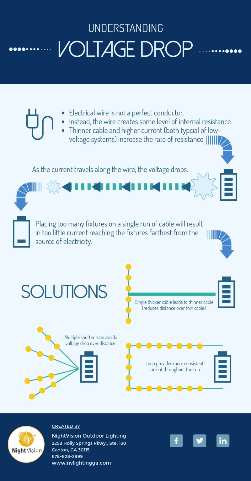
Understanding the Fundamentals of Voltage and Current
To grasp what causes voltage loss, it’s essential to first establish a solid understanding of the basic concepts of electricity: voltage, current, and resistance. These three elements are inextricably linked, forming the bedrock of all electrical circuits.
Defining Voltage and Current
Voltage (V), also known as electrical potential difference, electromotive force (EMF), or electrical pressure, is the force that pushes electrons through a circuit. It is the work done per unit of charge and is measured in volts. Think of it like the pressure in a water pipe: the higher the voltage, the greater the potential to drive current.
Current (I), on the other hand, is the flow rate of electric charge. It represents the number of electrons passing a given point in a circuit per unit of time, measured in amperes (amps). Following the water analogy, current is the volume of water flowing through the pipe.
The Role of Resistance in Electrical Circuits
Resistance (R) is the opposition to the flow of electric current. Every material has some degree of resistance, which converts electrical energy into other forms, primarily heat. Conductors like copper have very low resistance, allowing current to flow easily, while insulators like rubber have very high resistance, impeding current flow. Resistance is measured in ohms (Ω). In our water analogy, resistance would be the friction within the pipe or any narrowings that restrict water flow.
Ohm’s Law and Power Dissipation
The relationship between voltage, current, and resistance is elegantly described by Ohm’s Law: $V = I times R$. This fundamental law states that the voltage across a conductor is directly proportional to the current flowing through it, given a constant resistance.
When current flows through a resistor, electrical energy is converted into heat. This phenomenon is known as power dissipation, calculated by the formula $P = V times I$ or, substituting Ohm’s Law, $P = I^2 times R$. This $I^2R$ loss is paramount to understanding voltage loss, as it directly quantifies the energy wasted as heat, which often manifests as a reduction in available voltage. In essence, as power is dissipated across a resistive element, the voltage “drops” across that element, becoming unavailable to the rest of the circuit.
Primary Mechanisms of Voltage Loss
Voltage loss is not a singular phenomenon but rather a multifaceted issue stemming from several distinct electrical principles. While resistive losses are perhaps the most common, inductive and capacitive reactances also play significant roles, especially in alternating current (AC) circuits.
Resistive Losses ($I^2R$ Losses)
The most prevalent cause of voltage loss is resistive loss, often referred to as $I^2R$ losses. As current flows through any conductor, it encounters resistance, leading to the dissipation of energy as heat and a consequent drop in voltage. This loss is directly proportional to the square of the current and the resistance of the conductor.
Wire Gauge and Length
The physical dimensions of a conductor significantly impact its resistance. Wire gauge refers to the diameter of a wire; a smaller gauge number indicates a larger wire diameter. Thicker wires (smaller gauge numbers) have less resistance per unit length because they offer a larger cross-sectional area for electrons to flow through. Conversely, thinner wires have higher resistance and thus greater voltage loss for the same current. Similarly, the length of a conductor directly affects its total resistance. The longer the wire, the more resistance it presents, and consequently, the greater the voltage drop. This is why long extension cords or extensive building wiring can lead to noticeable voltage drops, particularly with high-current appliances.
Material Conductivity
The intrinsic property of the material used for the conductor also plays a crucial role. Materials like copper and aluminum are excellent conductors, meaning they have low resistivity. Silver is even better but prohibitively expensive for most applications. Materials with higher resistivity, such as nichrome used in heating elements, are deliberately chosen for their resistance, but using them unintentionally for power transmission would result in severe voltage loss.
Temperature Effects
Temperature has a significant impact on a conductor’s resistance. For most metallic conductors, resistance increases with increasing temperature. This means that a wire carrying current in a hot environment or a wire that heats up due to $I^2R$ losses will exhibit even greater resistance and, consequently, greater voltage loss. This positive temperature coefficient of resistance is a critical consideration in system design, especially in high-power applications or enclosed spaces.
Inductive Reactance and AC Circuits
In alternating current (AC) circuits, additional mechanisms contribute to voltage loss beyond simple resistance. One significant factor is inductive reactance ($X_L$), which arises from inductors and the magnetic fields they produce.
Magnetic Fields and Inductors
When an AC current flows through a conductor, it creates a constantly changing magnetic field around it. If this conductor is coiled into an inductor, or even if it’s just a long wire, this changing magnetic field induces a counter-electromotive force (CEMF) that opposes the change in current. This opposition to current flow is called inductive reactance, measured in ohms. Unlike resistance, which dissipates energy as heat, inductive reactance stores energy in the magnetic field and then releases it back to the circuit, causing a phase shift between voltage and current.
Frequency Dependence
Inductive reactance is directly proportional to the frequency of the AC current. At higher frequencies, the magnetic field changes more rapidly, leading to a greater induced CEMF and thus higher inductive reactance. This means that voltage loss due to inductance becomes more pronounced in high-frequency AC applications. Transmission lines, motors, and transformers all exhibit significant inductive properties that contribute to voltage drop, especially over long distances or at high power levels.
Capacitive Reactance and AC Circuits
Another AC-specific factor is capacitive reactance ($X_C$), which arises from capacitors and the electric fields they store.
Electric Fields and Capacitors
A capacitor consists of two conductive plates separated by a dielectric (insulating) material. When an AC voltage is applied, charge builds up on the plates, creating an electric field. This charging and discharging action causes the current to lead the voltage, effectively opposing changes in voltage. This opposition is capacitive reactance. Like inductive reactance, it is measured in ohms and causes a phase shift between voltage and current.
Impact on Power Factor
Unlike inductive reactance, capacitive reactance is inversely proportional to the frequency. At higher frequencies, a capacitor has less time to charge and discharge, offering less opposition to current flow (lower $X_C$). While large capacitors can be sources of voltage loss, their primary role in voltage management often involves compensating for inductive loads to improve the power factor. A poor power factor (due to high inductive loads) means that the current and voltage are out of phase, leading to more current being drawn than is actually used for work, thus increasing $I^2R$ losses upstream in the system even if the voltage drop across the load itself isn’t purely resistive. By adding capacitance, the phase difference can be reduced, improving power factor and effectively reducing overall system voltage loss and improving efficiency.
Factors Contributing to Voltage Drop in Practical Systems
Beyond the fundamental mechanisms, several practical considerations in real-world electrical systems exacerbate voltage loss. These factors highlight the complexity of designing and maintaining efficient power delivery networks.
Conductor Properties (Material, Gauge, Length)
As discussed, the choice of conductor material (e.g., copper vs. aluminum), its physical dimensions (wire gauge), and the total length of the wire are paramount. Using undersized wires for a given current load, or excessively long cable runs, will inevitably lead to significant voltage drop. Building codes and electrical standards provide guidelines for minimum wire gauges for various applications to prevent dangerous overheating and unacceptable voltage loss.
Load Characteristics and Power Demand
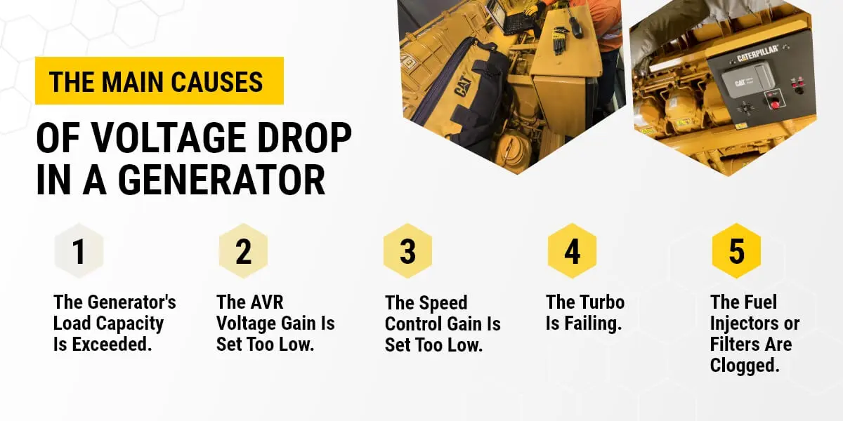
The nature and magnitude of the electrical load connected to a circuit are direct drivers of voltage loss. Higher current draw, whether from a single powerful appliance or multiple devices operating simultaneously, will proportionally increase the $I^2R$ losses in the supply wiring. Motors, for instance, have high inrush currents upon starting, which can cause momentary, significant voltage drops across an entire circuit. Inductive loads like motors and transformers also contribute to a poor power factor, demanding more reactive power from the source and thus higher currents, further increasing $I^2R$ losses in the distribution system.
Connection Points and Contact Resistance
Often overlooked, the quality of electrical connections can be a major source of voltage drop. Every splice, terminal block, connector, or switch introduces a small amount of contact resistance. While individually small, a series of poor connections can accumulate to a substantial total resistance. Loose, corroded, or improperly made connections can significantly impede current flow, generating heat and causing localized voltage drops. This is particularly problematic in older wiring systems or in environments with high humidity or corrosive elements.
Environmental Factors (Temperature, Moisture)
Environmental conditions can exacerbate voltage loss. High ambient temperatures increase the resistance of conductors, leading to greater $I^2R$ losses. Excessive moisture or humidity can lead to corrosion at connection points, increasing contact resistance, or even create unintended conductive paths (leakage currents) that divert power. Extreme cold, while generally reducing resistance, can make materials brittle and connections prone to failure.
Power Supply Quality and Source Impedance
The power source itself is not always ideal. Every power supply, whether a battery, generator, or the utility grid, has an internal source impedance (equivalent internal resistance and reactance). This internal impedance means that as the current drawn from the supply increases, there will be a voltage drop within the supply itself, reducing the terminal voltage available to the load. A “weak” power supply with high internal impedance will show a much larger voltage drop under load compared to a “stiff” power supply with low internal impedance. Fluctuations in the grid voltage can also contribute to perceived or actual voltage loss at the point of use.
Consequences and Mitigation Strategies for Voltage Loss
The effects of voltage loss range from minor inconveniences to severe system failures. Fortunately, various design considerations and technological solutions exist to mitigate these losses.
Impacts on System Performance and Efficiency
Voltage loss has several undesirable consequences:
Reduced Power Delivery
The most direct impact is a reduction in the actual power delivered to the load. If the voltage available at the device is significantly lower than its rated voltage, the device may operate inefficiently, perform below specifications, or even fail to start. For resistive loads like heaters, reduced voltage means less heat output. For motors, it means reduced torque and speed.
Increased Heat Generation
The energy lost as voltage drop across resistance is dissipated as heat. This not only represents wasted energy but can also lead to localized overheating of wires, connections, and components, potentially damaging insulation, increasing fire risk, or shortening the lifespan of equipment.
Malfunctioning Equipment
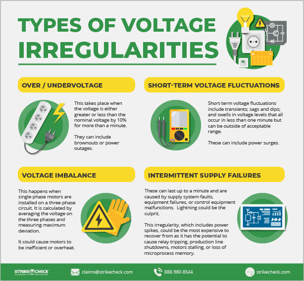
Many electronic devices are designed to operate within a specific voltage range. Significant voltage drops can cause microprocessors to reset, sensors to give inaccurate readings, motors to stall, or lights to flicker. In sensitive control systems, unstable voltage can lead to unpredictable behavior and system failures.
Design Considerations for Minimizing Loss
Effective system design is the primary defense against excessive voltage loss.
Proper Wire Sizing
Adhering to electrical codes and engineering standards for wire sizing is crucial. Calculating the expected current load, considering the conductor length, and selecting an appropriate wire gauge ensures that resistance is minimized, and voltage drop remains within acceptable limits (typically 2-5% for most applications).
Shortening Conductor Lengths
Where possible, minimizing the distance between the power source and the load directly reduces the total resistance of the conductors, thereby decreasing voltage loss. This is a fundamental principle in power distribution network design.
Utilizing Higher Voltages for Transmission
For long-distance power transmission, utilities employ extremely high voltages (e.g., hundreds of kilovolts). This is because for a given amount of power ($P=V times I$), increasing the voltage allows the current ($I$) to be proportionally reduced. Since power loss is proportional to $I^2R$, reducing the current drastically reduces the $I^2R$ losses, even over very long distances. Step-up transformers are used at the generating station, and step-down transformers are used near consumers.
Advanced Techniques and Technologies
Beyond fundamental design, several technologies actively address voltage loss.
Power Factor Correction
For AC systems with significant inductive loads, power factor correction (PFC) is vital. This involves adding capacitors to the circuit to counteract the inductive reactance, bringing the current and voltage phases closer into alignment. Improving the power factor reduces the total current that needs to be drawn from the source for the same amount of real power, thereby decreasing $I^2R$ losses in the distribution system and improving overall efficiency.
Voltage Regulators and Stabilizers
Voltage regulators are electronic circuits or devices that maintain a constant output voltage regardless of fluctuations in the input voltage or load current. They are essential for sensitive electronics. Voltage stabilizers are similar devices used in homes or industries to protect equipment from utility voltage fluctuations, ensuring a steady supply even if there are brownouts or overvoltages upstream.
Distributed Power Systems
Instead of relying on a single central power source, distributed power systems utilize multiple, smaller power sources located closer to the loads (e.g., rooftop solar panels, local micro-grids). This strategy significantly reduces the length of transmission lines and consequently minimizes voltage loss inherent in long-distance power delivery.
The Broader Impact on Technology and Everyday Life
Voltage loss is not merely an engineering challenge; its implications ripple through various technological domains and directly affect energy efficiency and sustainability efforts.
From Microelectronics to Grid Systems
In microelectronics, even tiny voltage drops across traces on a circuit board or within a chip can disrupt delicate logic circuits or lead to errors. Power integrity is a critical design consideration, especially in high-speed digital circuits. For large-scale grid systems, minimizing voltage loss is essential for economic viability and grid stability. Excessive losses can lead to brownouts, blackouts, and substantial economic penalties for utilities.
Energy Efficiency and Sustainability
Every watt lost to voltage drop represents wasted energy. In an era where energy conservation and environmental responsibility are paramount, reducing voltage loss directly contributes to greater energy efficiency. Less energy waste means a smaller carbon footprint and a more sustainable use of finite resources. Utilities are constantly investing in smart grid technologies, higher-efficiency transformers, and advanced conductor materials to minimize these losses.
Future Innovations in Power Delivery
The ongoing quest to reduce voltage loss drives innovation across the electrical engineering landscape. Research into superconducting materials (which have zero electrical resistance at very low temperatures) promises zero voltage loss transmission, though practical applications are still largely experimental due to cooling challenges. Advances in wireless power transfer technologies aim to eliminate physical conductors altogether for certain applications, circumventing traditional voltage drop issues. Furthermore, the development of more efficient power electronics and sophisticated control algorithms continues to push the boundaries of energy transmission and management.
In conclusion, voltage loss is an inherent aspect of electrical systems, dictated by the fundamental laws of physics. Its causes are diverse, ranging from the intrinsic resistance of conductors to the reactive properties of AC circuits and practical design choices. Recognizing and mitigating these causes through careful design, material selection, and advanced technologies is not just an engineering best practice; it is a critical endeavor that underpins the reliability, efficiency, and sustainability of our increasingly electrified world.
aViewFromTheCave is a participant in the Amazon Services LLC Associates Program, an affiliate advertising program designed to provide a means for sites to earn advertising fees by advertising and linking to Amazon.com. Amazon, the Amazon logo, AmazonSupply, and the AmazonSupply logo are trademarks of Amazon.com, Inc. or its affiliates. As an Amazon Associate we earn affiliate commissions from qualifying purchases.