
DXF, or Drawing Exchange Format, stands as a pivotal file format within the realm of Computer-Aided Design (CAD) and digital graphics. Developed by Autodesk, the creators of AutoCAD, DXF was conceived as a bridge, a universal translator designed to facilitate data exchange between different CAD software applications. In an industry where proprietary file formats can create significant barriers to collaboration and workflow efficiency, DXF emerged as a solution, enabling users to share designs, drawings, and geometric data with a broad spectrum of software, from high-end professional CAD suites to more accessible design tools.
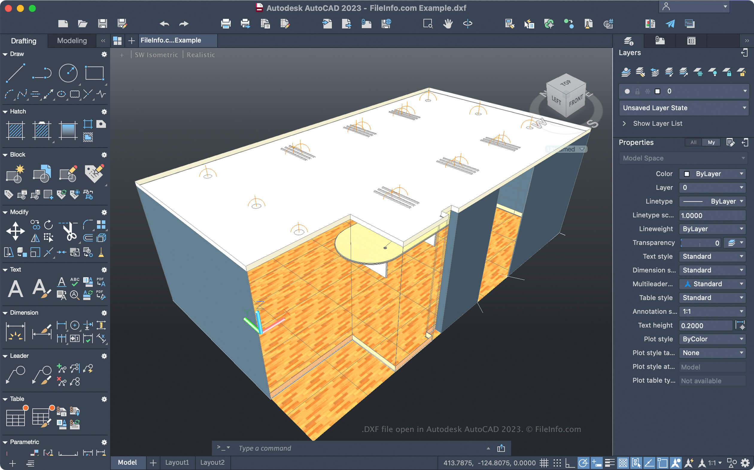
At its core, a DXF file is a vector-based representation of graphical data. Unlike raster images (like JPEGs or PNGs) which are composed of pixels, vector graphics are defined by mathematical equations that describe lines, curves, shapes, and their properties. This fundamental difference means that DXF files can be scaled infinitely without any loss of quality, a critical advantage for technical drawings, architectural plans, and engineering schematics where precision is paramount. Understanding the nature and structure of DXF files is essential for anyone working in design, manufacturing, architecture, engineering, or even hobbyist fields that involve digital creation and precision.
The enduring relevance of DXF lies in its open nature, at least compared to many other CAD formats. While originally proprietary, Autodesk has largely kept the DXF specification public, allowing developers to create software that can read and write DXF files. This has fostered a rich ecosystem of compatible software, making DXF a de facto standard for inter-application data transfer in many design-centric industries.
The Genesis and Evolution of the DXF Format
The need for a standardized data exchange format in the burgeoning CAD industry became apparent in the early days of digital design. As more software emerged, each with its own way of storing geometric information, users found themselves trapped within their chosen software ecosystem. Sharing designs with collaborators using different programs was often a complex, error-prone, and time-consuming process, frequently involving manual redrawing or the use of clunky import/export utilities.
Addressing the Interoperability Challenge
Autodesk recognized this critical bottleneck in the CAD workflow. In 1982, with the release of AutoCAD 1.2, they introduced the DXF format. The primary objective was to provide a neutral, text-based representation of AutoCAD drawing files, allowing them to be imported and exported by other programs. This was a groundbreaking initiative that significantly eased the friction in design collaboration.
From ASCII to Binary and Back Again
The initial versions of DXF were primarily ASCII-based, meaning the file content was human-readable text. This made debugging and understanding the file structure relatively straightforward. However, ASCII files are larger and can be slower to parse compared to binary formats. As CAD files grew in complexity and size, the need for more efficient storage and retrieval became evident.
Over time, Autodesk introduced binary DXF formats, which offered a more compact and faster way to store and read drawing data. While binary DXF is not human-readable, it significantly improved performance for large and complex drawings. Today, both ASCII and binary versions of DXF are supported, offering flexibility depending on the user’s needs and the capabilities of the software they are using. The ongoing development and support of the format by Autodesk, coupled with its widespread adoption, have cemented DXF’s position as a stalwart in digital design data exchange.
The Structure and Components of a DXF File
Understanding the underlying structure of a DXF file provides valuable insight into how it stores and represents complex geometric information. While the intricacies can be extensive, a general understanding of its organization into sections and the types of data it can contain is crucial for effective use. DXF files are essentially structured text files (or binary equivalents) that describe graphical entities and their associated properties.
Section-Based Organization
A DXF file is organized into several distinct sections, each serving a specific purpose. These sections are clearly delimited and contain specific types of information. The primary sections include:
- HEADER Section: This section contains general information about the drawing, such as units, limits, grid settings, and other system variables. It’s akin to the metadata of the drawing file.
- CLASSES Section: This section is less commonly encountered by end-users but is used to store information about application-defined classes, particularly relevant for complex object data and custom entities.
- TABLES Section: This is a crucial section that defines various named elements used within the drawing. This includes:
- LAYER Table: Defines the layers in the drawing, their names, colors, linetypes, and plot styles.
- LTYPE Table: Defines linetype definitions (e.g., dashed, dotted, center lines).
- STYLE Table: Defines text styles (font, height, oblique angle, etc.).
- VIEW Table: Stores named views that the user has saved.
- UCS Table: Defines User Coordinate Systems.
- APPID Table: Defines application-defined object IDs.
- DIMSTYLE Table: Defines dimension style settings.
- BLOCK Table: Defines block definitions.
- BLOCKS Section: This section contains the definitions of all blocks within the drawing. Blocks are reusable groups of entities that can be inserted multiple times.
- ENTITIES Section: This is the most significant section, as it contains the actual graphical entities that make up the drawing. This includes lines, arcs, circles, polylines, text, dimensions, and more. Each entity has specific attributes like coordinates, color, layer, and linetype.
- OBJECTS Section: This section stores non-graphical objects, such as dictionaries, application-defined data, and other extended entity data.
- THUMBNAILIMAGE Section: Some DXF files may contain a preview image of the drawing.
Data Representation: Group Codes
Within each section, data is represented using pairs of “group codes” and their corresponding “values.” A group code is a numerical integer that specifies the type of data that follows, and the value is the actual data itself. For example, group code 10 might indicate the X-coordinate of a point, and the following value would be the numerical X-coordinate. This structured approach allows software to parse and interpret the geometric and attribute data systematically.
Common Geometric Entities
The ENTITIES section is populated with various geometric primitives. Some of the most commonly supported entities in DXF include:
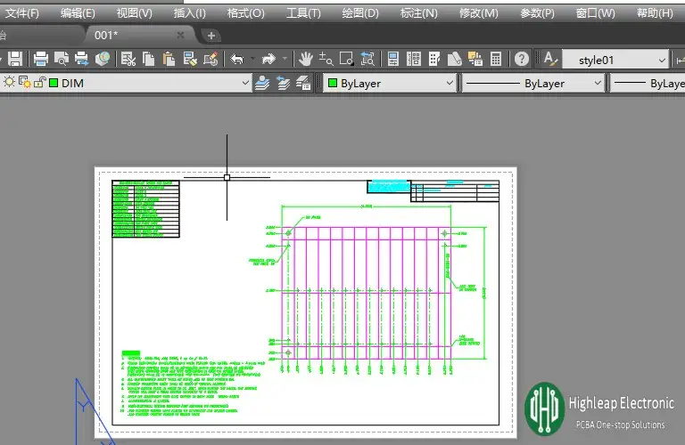
- LINE: A straight line segment defined by its start and end points.
- ARC: A portion of a circle defined by its center, radius, start angle, and end angle.
- CIRCLE: A full circle defined by its center and radius.
- POLYLINE: A series of connected line and arc segments forming a complex shape.
- TEXT: Textual information placed within the drawing.
- INSERT: An instance of a block definition placed in the drawing.
- HATCH: A pattern or fill applied to enclosed areas.
The ability to represent these diverse entities and their properties is what makes DXF so versatile.
Applications and Workflows Empowered by DXF
The universal nature of DXF files has made them indispensable across a wide spectrum of industries and applications. Its primary strength lies in its ability to act as a common language for design data, facilitating seamless integration between disparate software tools and streamlining complex workflows.
Bridging Software Gaps in Design and Engineering
The most prominent use of DXF is in enabling interoperability between different CAD software packages. Architects using Revit can export their building designs to DXF for structural engineers using SolidWorks, who can then use that data to machine parts. Similarly, a graphic designer using Adobe Illustrator might import a DXF file from a CAD program to incorporate precise technical elements into a marketing brochure or product visualization.
This ability to move data freely avoids the costly and time-consuming process of re-creating designs from scratch or relying on less precise image formats. It ensures that critical design intent, measurements, and geometric relationships are preserved.
Fueling Manufacturing and Fabrication Processes
In the manufacturing and fabrication sectors, DXF files are fundamental to the production pipeline. CNC (Computer Numerical Control) machines, such as laser cutters, plasma cutters, vinyl plotters, and CNC routers, often read instructions directly from DXF files. The vector data within a DXF precisely outlines the shapes to be cut, ensuring accuracy and efficiency in production.
For instance, a metal fabricator might receive a DXF file of a custom bracket from an engineering firm. This file will guide the laser cutter to precisely cut the bracket from a sheet of metal, saving time and minimizing material waste. The same applies to sign makers using vinyl plotters or woodworkers creating intricate designs.
Applications in 3D Printing and Hobbyist Projects
While DXF is fundamentally a 2D format, it is also widely used in workflows for 3D printing. Many 3D modeling software packages can export designs in DXF format, which can then be processed by slicer software for 3D printers. This is particularly common for creating molds, stencils, or flat components that will be assembled into a 3D object.
Hobbyists and makerspaces also benefit immensely from DXF. The accessibility of DXF-compatible software, including many free and open-source options, allows individuals to design and create intricate projects, from custom jigs for woodworking to personalized decorations, with precision.
Advantages and Limitations of the DXF Format
Like any technology, DXF comes with its own set of strengths and weaknesses. Understanding these nuances is crucial for making informed decisions about when and how to best utilize this widely adopted file format.
Strengths: Universality, Precision, and Accessibility
- Universal Compatibility: The foremost advantage of DXF is its broad compatibility. It is supported by hundreds of CAD programs, graphic design software, CAM (Computer-Aided Manufacturing) software, and even many general-purpose drawing applications. This makes it the go-to format for sharing design data across different platforms and teams.
- Vector-Based Precision: As a vector format, DXF files store geometric information mathematically. This allows designs to be scaled infinitely without any degradation in quality, ensuring that critical dimensions and details remain sharp and accurate, regardless of the viewing or manufacturing scale.
- Open Standard (Relatively): While developed by Autodesk, the DXF specification has been largely publicly available, fostering widespread adoption and enabling third-party software developers to create compatible tools. This openness has contributed significantly to its longevity.
- ASCII Option for Readability and Debugging: The ASCII version of DXF, while larger, is human-readable. This can be invaluable for troubleshooting issues, understanding file structure, or even making minor manual edits to the data.
Weaknesses: Data Loss, Complexity, and Lack of 3D Richness
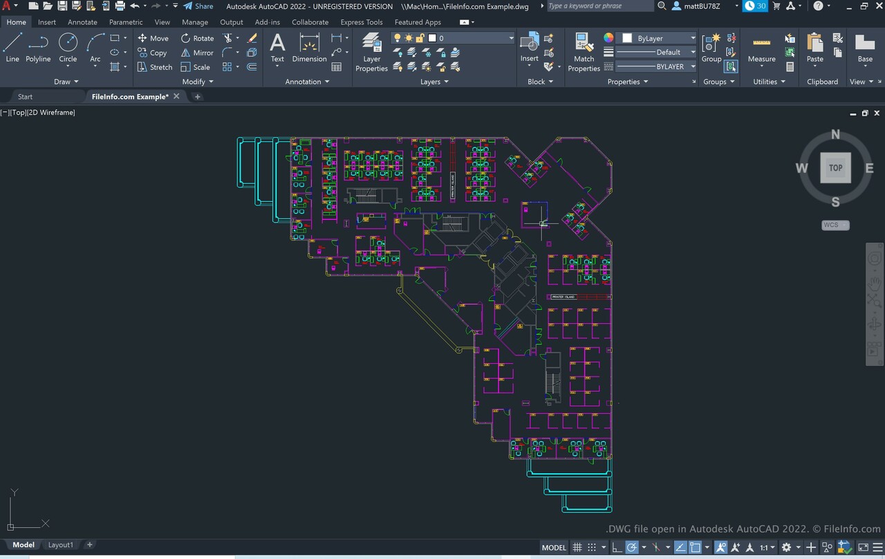
- Potential for Data Loss and Interpretation Issues: While designed for exchange, DXF is not always a perfect translator. Complex entities, advanced surfacing data, or proprietary features specific to one CAD program might not be fully supported or accurately translated by all other applications. This can lead to subtle differences or outright data loss in the exported file.
- Limited Richness for Complex 3D Data: DXF is primarily a 2D drawing format. While it can represent some 3D entities (like 3D faces, solids, and meshes), it is not as robust or feature-rich for complex three-dimensional modeling as formats like STEP, IGES, or native CAD files (e.g.,
.dwg,.sldprt). Sharing highly detailed 3D models often requires formats designed specifically for that purpose. - File Size Inefficiencies: Especially with ASCII versions, DXF files can become quite large, particularly for complex drawings with many entities. This can impact storage space and transfer times. Binary DXF mitigates this to some extent but remains less compact than some other formats.
- Overhead for Simple Graphics: For very simple graphics or icons, a DXF file might be overkill compared to more lightweight formats like SVG.
Despite its limitations, DXF remains an indispensable tool for anyone involved in design, engineering, and manufacturing. Its ability to facilitate cross-platform collaboration and its direct application in fabrication processes ensure its continued relevance in the digital creation landscape.
aViewFromTheCave is a participant in the Amazon Services LLC Associates Program, an affiliate advertising program designed to provide a means for sites to earn advertising fees by advertising and linking to Amazon.com. Amazon, the Amazon logo, AmazonSupply, and the AmazonSupply logo are trademarks of Amazon.com, Inc. or its affiliates. As an Amazon Associate we earn affiliate commissions from qualifying purchases.