
In an age defined by instant communication and data-intensive applications, the backbone of our digital infrastructure is more critical than ever. While traditional copper cables have long served as the workhorses of connectivity, they are increasingly being outpaced by the insatiable demands of modern technology. Enter fiber optic cable: a revolutionary medium that transmits data as pulses of light, offering unparalleled speed, bandwidth, and reliability. Whether you’re upgrading a home network, setting up a small office, or deploying a robust industrial system, understanding how to install fiber optic cable is a valuable skill that empowers you to build a future-proof network.
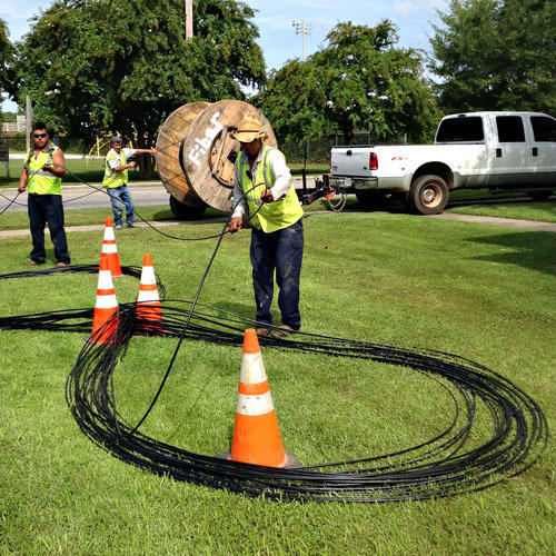
This comprehensive guide delves into the intricacies of fiber optic installation, providing a step-by-step tutorial designed for both enthusiasts and professionals. We’ll cover everything from initial planning and essential tool selection to the delicate art of termination and rigorous testing procedures. By the end of this article, you’ll possess the knowledge to confidently embark on your own fiber optic cabling project, unlocking the full potential of your digital connections.
Understanding Fiber Optics: Why Make the Switch?
Before diving into the practicalities of installation, it’s crucial to grasp why fiber optics are becoming the preferred choice for high-performance networks. The benefits extend far beyond mere speed, touching upon aspects like security, longevity, and overall system efficiency – all pertinent to the “Tech” focus of our website.
The Unmatched Advantages of Fiber
Fiber optic cables utilize hair-thin strands of glass or plastic to transmit data via light signals, a fundamentally different approach to copper’s electrical signals. This difference translates into several profound advantages:
- Blazing Speeds and Immense Bandwidth: Fiber optics can carry vastly more data at significantly higher speeds over longer distances compared to copper. This is crucial for bandwidth-hungry applications like 4K/8K video streaming, cloud computing, online gaming, and large data transfers, ensuring your network doesn’t become a bottleneck for productivity.
- Extended Reach: Light signals degrade much less over distance than electrical signals. Fiber can transmit data reliably for kilometers without the need for signal boosters, making it ideal for large campuses, inter-building connections, or sprawling industrial facilities.
- Immunity to Electromagnetic Interference (EMI): Unlike copper, fiber optic cables are not affected by electromagnetic interference from power lines, machinery, or radio frequencies. This makes them exceptionally reliable in electrically noisy environments and ensures consistent, error-free data transmission – a significant advantage for digital security and system stability.
- Enhanced Security: Since fiber optics transmit light and do not emit electromagnetic signals, they are much harder to tap into clandestinely without detection. Any attempt to physically intercept a fiber optic cable will typically cause a noticeable attenuation of the light signal, making it easier to identify and prevent data breaches. This is a critical security feature for sensitive data environments.
- Durability and Longevity: While glass can seem fragile, fiber optic cables, especially those designed for outdoor or industrial use, are incredibly robust. They are resistant to temperature fluctuations, moisture, and even some corrosive chemicals, promising a longer operational lifespan and reducing maintenance overheads.
- Future-Proofing Your Infrastructure: With the continuous explosion of data and the rise of IoT, AI, and advanced multimedia, fiber optic infrastructure provides the necessary headroom to accommodate future technological advancements without requiring costly upgrades to your physical cabling.
Deciding on Your Fiber Optic Needs
The first step in any installation project is to clearly define your objectives. What kind of network are you building, and what are its primary requirements?
- Application: Are you connecting two buildings, wiring a smart home, or building a data center? The application will dictate the type of cable, connectors, and overall network architecture.
- Distance: How far will the cable run? Distances under a few hundred meters might tolerate multi-mode fiber, while longer runs definitely require single-mode fiber.
- Environment: Will the cable be indoors or outdoors? Buried underground, strung aerially, or run through conduits? This affects the cable’s jacket material, strength members, and armoring.
- Speed Requirements: While fiber inherently offers high speeds, the specific equipment (transceivers, switches) will determine the actual achievable data rates (e.g., 1Gbps, 10Gbps, 100Gbps, 400Gbps).
- Budget: Fiber optic installation can be an investment. Understand the costs associated with materials, tools, and potentially professional labor. Balancing performance with cost-effectiveness is key.
Careful consideration of these factors will guide your choices in cable type, termination methods, and overall network design, laying a solid foundation for a successful installation.
Essential Preparation: Tools, Materials, and Planning Your Route
A successful fiber optic installation hinges on meticulous planning and having the right equipment. Rushing this stage often leads to costly errors, damaged cables, and unreliable networks.
Selecting the Right Fiber Optic Cable Type
The world of fiber optics offers a variety of cable types, each suited for specific applications. Understanding the distinctions is crucial:
- Single-Mode Fiber (SMF): Features a very small core (8-10 microns) that allows only a single path for light to travel. This minimizes signal dispersion, enabling extremely high bandwidth and data transmission over vast distances (tens to hundreds of kilometers). SMF is ideal for long-haul networks, high-speed data centers, and internet service provider backbones. It often uses laser light sources.
- Multi-Mode Fiber (MMF): Has a larger core (50 or 62.5 microns) that allows multiple paths for light to travel. While more affordable for shorter distances (up to a few hundred meters) and easier to work with, MMF experiences modal dispersion, limiting its reach and ultimate bandwidth compared to SMF. It commonly uses LED or VCSEL light sources and is prevalent in local area networks (LANs) within buildings or campuses.
- OM1, OM2, OM3, OM4, OM5: These are classifications for multi-mode fiber, indicating their bandwidth capabilities and maximum distances for various Ethernet speeds. Newer generations like OM4 and OM5 offer significantly improved performance.
- Cable Jacket Types:
- Indoor Cables: Typically have PVC or LSZH (Low Smoke Zero Halogen) jackets, designed for fire safety within buildings. Examples include simplex, duplex, distribution, and breakout cables.
- Outdoor Cables: Feature more robust, UV-resistant, moisture-resistant, and often armored jackets (e.g., PE – polyethylene) to withstand harsh environmental conditions. They can be direct-buried, aerial, or placed in conduits.
- Armored vs. Non-Armored: Armored cables contain a layer of steel or aramid yarn for increased protection against crushing, rodent damage, and impact, making them essential for harsh environments or direct burial.
Gathering Your Fiber Optic Installation Toolkit
Fiber optic work requires specialized tools due to the precision and delicacy involved. A basic toolkit should include:
- Fiber Optic Strippers: Multi-hole strippers designed to remove the outer jacket, buffer tube, and the 250-micron coating from the optical fiber without damaging the delicate glass cladding.
- Fiber Cleaver: This is arguably the most critical tool. A high-precision cleaver makes a perfectly flat, clean, and perpendicular cut on the fiber end-face, which is essential for low-loss splices and connections. Poor cleaves are a primary cause of high attenuation.
- Fusion Splicer (Optional but Recommended for Professional Results): A fusion splicer precisely aligns two fiber ends and then melts them together using an electric arc, creating a permanent, near-lossless connection. While expensive, it offers the best performance and reliability.
- Mechanical Connectors (Alternative to Splicing): These connectors allow field termination without a fusion splicer. They typically use an internal gel or epoxy to mechanically hold and align cleaved fibers, offering a quicker but sometimes higher-loss alternative.
- Inspection Microscope/Scope: Used to visually inspect the fiber end-face for dirt, scratches, or imperfections before connection. Contamination is the leading cause of signal loss.
- Optical Power Meter (OPM) and Light Source (OLS): Used together to measure the optical power loss (attenuation) of a fiber link, ensuring it meets performance specifications.
- Optical Time Domain Reflectometer (OTDR): A sophisticated tool that sends light pulses down the fiber and analyzes the reflected light to locate faults (breaks, splices, connectors), measure distances, and characterize the overall health of the fiber link. Essential for troubleshooting and certification.
- Fiber Optic Cleaning Supplies: Lint-free wipes, specialized solvent (e.g., isopropyl alcohol), and “click” cleaners are indispensable for cleaning fiber end-faces and connectors.
- Safety Glasses and Gloves: Always wear appropriate personal protective equipment. Fiber shards are extremely sharp and can cause serious injury if they get into your eyes or skin.
- Cable Ties, Straps, Labels: For proper cable management and organization.
- Splice Trays and Enclosures: To protect fusion splices and fiber optic connectors from physical damage and environmental elements.
Meticulous Route Planning and Safety Protocols
Before pulling any cable, thorough planning of the route is paramount:

- Survey the Path: Identify obstacles, potential pinch points, existing infrastructure, and access points. Plan for minimum bend radius requirements for fiber optic cable to avoid signal loss (typically 10-20 times the cable diameter, but always check manufacturer specs).
- Conduits and Cable Trays: Whenever possible, use conduits or cable trays, especially for indoor runs. They protect the cable, make future upgrades easier, and improve organization. Ensure conduits are clean and free of sharp edges.
- Outdoor Considerations: For outdoor installations, consider direct burial (requires armored cable and proper trenching), aerial installation (requires appropriate messenger wire and hardware), or placing in underground ducts. Ensure compliance with local regulations and utility markings.
- Pulling Techniques: Plan for gentle pulling. Fiber optic cables have a maximum tensile load that must not be exceeded. Use pulling lubricants, swivel pulling eyes, and intermediate pull boxes for long or complex runs.
- Safety First: Beyond personal protective equipment, ensure a clean work area. Dispose of fiber shards properly (e.g., in a labeled container). Never look directly into an active fiber, as invisible laser light can damage your eyes.
Step-by-Step Installation: From Laying to Termination
With planning complete and tools ready, the actual installation process can begin. This stage requires patience, precision, and adherence to best practices.
Running and Securing the Fiber Optic Cable
The way you handle and route the cable significantly impacts its performance and longevity.
- Preparation of the Cable End: Before pulling, attach a pulling eye to the cable end. This often involves stripping back some of the jacket, exposing the strength members (like aramid yarn), and securing them to the pulling eye. This transfers the pulling tension to the strength members, protecting the delicate optical fibers.
- Pulling the Cable:
- Constant Tension: Maintain a steady, even pulling tension. Avoid sudden jerks or exceeding the cable’s maximum tensile rating. Use a pulling winch with tension control for long runs.
- Lubrication: For conduit runs, apply appropriate cable lubricant to reduce friction.
- Intermediate Pulls: For very long or complex runs with multiple bends, it’s often necessary to perform intermediate pulls from pull boxes to manage tension and prevent damage.
- Avoid Kinks and Twists: Fiber optic cables are extremely sensitive to tight bends and kinks. Always maintain the cable’s minimum bend radius throughout the pulling process.
- Securing and Managing the Cable:
- Slack Management: Leave appropriate service loops or slack at termination points (e.g., patch panels, enclosures). This provides flexibility for future maintenance, re-termination, or moves, adds, and changes (MACs).
- Routing and Support: Use appropriate cable ties, straps, and clamps to secure the cable along its route, preventing it from sagging or getting pinched. Avoid over-tightening ties, which can deform the cable.
- Labeling: Clearly label both ends of the cable with source and destination information. This is invaluable for troubleshooting and maintenance, especially in complex networks.
Precision Termination: Splicing vs. Connecting
Once the cable is run, the next critical step is termination – attaching connectors or splicing cables together. This is where the light path is created or extended, and it demands the highest level of precision.
- Stripping the Cable: Carefully remove the outer jacket, strength members, and buffer tubes according to the connector or splice tray manufacturer’s instructions. This exposes the individual optical fibers, typically with a 250-micron coating.
- Cleaning the Fiber: Before cleaving, gently clean the exposed fiber using a lint-free wipe and isopropyl alcohol. Any dust or residue can compromise the cleave quality.
- Cleaving the Fiber: This is a crucial step. The fiber cleaver precisely scores and breaks the fiber, creating a perfectly flat, clean, and perpendicular end-face. A bad cleave (angled, chipped, or stepped) will result in high insertion loss and poor performance. Follow the cleaver’s specific instructions, ensuring the fiber is positioned correctly and the blade is clean.
- Connecting the Fibers:
- Fusion Splicing: This is the preferred method for permanent, low-loss connections.
- Alignment: The fusion splicer automatically aligns the two cleaved fiber ends with incredible precision.
- Fusion: An electric arc then melts the glass ends together, creating a continuous, monolithic fiber.
- Protection: The splice is then protected with a heat-shrinkable splice protector sleeve, which is cured in the splicer’s oven. These protected splices are then housed within splice trays inside an enclosure.
- Mechanical Connectors: These are often used for field termination where a fusion splicer is unavailable or for quick repairs.
- Preparation: After cleaving, the fiber is inserted into the connector’s pre-polished ferrule.
- Alignment: An internal mechanism (often with a refractive index matching gel) aligns the newly inserted fiber with a short stub of fiber already fixed within the connector.
- Securing: The fiber is then crimped or locked into place. While faster, mechanical connectors generally have higher insertion loss and back reflection compared to fusion splices.
- Pre-terminated Cables: For simpler installations or shorter runs, pre-terminated fiber optic cables with factory-attached connectors offer a plug-and-play solution, eliminating the need for field termination. You simply connect them to patch panels or equipment.
- Fusion Splicing: This is the preferred method for permanent, low-loss connections.
Rigorous Testing and Verification for Optimal Performance
Installation isn’t complete until the network is thoroughly tested and verified. This ensures the integrity of your work and the performance of your connections.
- Visual Inspection (Microscope): Always inspect the end-face of every connector before plugging it in. Use an inspection scope to check for dirt, scratches, pits, or epoxy residue. A dirty or damaged end-face is the most common cause of signal loss and can damage expensive transceivers. Clean as necessary with appropriate fiber cleaning tools.
- Optical Power Loss (Tier 1 Testing with OPM/OLS):
- Set a Loss Budget: Based on the length of the run, number of splices, and connectors, calculate the expected maximum allowable signal loss (dB).
- Reference Power: Connect the OLS to the OPM directly or via a short reference cable to establish a “0 dB” reference power.
- Test the Link: Connect the OLS to one end of the installed fiber link and the OPM to the other. The OPM will display the total insertion loss of the link.
- Compare to Budget: Ensure the measured loss is within the calculated loss budget. High loss indicates an issue (e.g., poor splice, dirty connector, bend radius violation).
- Optical Time Domain Reflectometer (Tier 2 Testing with OTDR):
- Fault Location: An OTDR is invaluable for characterizing the fiber link and pinpointing specific events like splices, connectors, and breaks. It provides a graphical trace of the fiber, showing the location and loss of each event.
- Link Integrity: It verifies the length of the cable, confirms the quality of splices and connectors, and helps identify any macro-bends or micro-bends that might be causing excessive attenuation. OTDR testing is often required for warranty and certification purposes.
- Documentation: Record all test results, including power loss measurements, OTDR traces, and cable labeling information. This documentation is crucial for future troubleshooting, maintenance, and network upgrades.
Best Practices, Maintenance, and Troubleshooting Common Issues
A well-installed fiber optic network is robust, but adhering to best practices and understanding potential pitfalls will maximize its lifespan and ensure consistent performance, contributing directly to productivity and reliability.
Maximizing Lifespan and Performance
- Cleanliness is King: The single most critical best practice in fiber optics. Always clean connectors before mating them, even if they appear clean. Dust, oil, and microscopic particles are the primary enemies of optical signals.
- Respect the Bend Radius: Never exceed the minimum bend radius specified by the cable manufacturer. Tight bends cause macro-bends, leading to significant signal loss and potential long-term damage to the fiber.
- Proper Cable Management: Use patch panels, fiber distribution units (FDUs), and splice enclosures to organize and protect fiber connections. Route patch cords neatly, using appropriate trays and channels. This not only improves aesthetics but also prevents accidental damage and simplifies maintenance.
- Protection of Exposed Fibers: Never leave stripped or cleaved fibers exposed. Always place them in splice trays or connectors immediately to prevent contamination and damage.
- Regular Inspections (Especially in High-Traffic Areas): For critical links, periodic inspection of connector end-faces can proactively identify issues before they cause outages.
- Environmental Control: While fiber is robust, extreme temperature fluctuations or moisture exposure can affect performance over time, especially in termination points. Ensure enclosures are properly sealed and environmental conditions are managed where possible.
Addressing Potential Pitfalls
Even with the best preparation, issues can arise. Knowing how to troubleshoot effectively minimizes downtime.
- High Insertion Loss:
- Dirty Connectors: The most common culprit. Re-clean all connectors in the affected link, especially the ones at both ends.
- Poor Cleaves/Splices: If an OTDR was used, it will pinpoint these. For mechanical connectors, re-cleave and re-terminate. For fusion splices, re-splice if necessary.
- Bend Radius Violation: Visually inspect the cable route for tight bends. Reroute or add slack to alleviate stress.
- Damaged Fiber: A sharp break or severe crush will show as a significant event on an OTDR. The fiber may need to be repaired (spliced) or replaced.
- Intermittent Connection: Often points to a loose or partially connected connector, or a fiber under stress that occasionally moves, causing signal fluctuations. Re-seat connectors, check cable routing.
- No Light/No Signal:
- Transceiver Issue: Check if the transmitting or receiving equipment is functioning correctly.
- Complete Break: Use a visual fault locator (VFL) for short distances or an OTDR for longer runs to quickly locate the break.
- Incorrect Cable Type/Mode Mismatch: Ensure single-mode cables are connected to single-mode equipment/cables, and multi-mode to multi-mode. Also verify OM types (e.g., OM3 to OM3).
- Power Budget Exceeded: If your OPM readings are consistently higher than your calculated loss budget, it means the overall loss is too high. This requires a systematic approach, checking each splice, connector, and section of the cable for excessive loss.

The Future is Fiber: Empowering Your Digital Infrastructure
Installing fiber optic cable is an investment in the future of your digital infrastructure. While the process demands precision and specialized tools, the resulting benefits in speed, reliability, and security are unparalleled. As technology continues its relentless march forward, demanding ever more bandwidth and resilience, fiber optics will remain at the forefront of connectivity.
By understanding the principles, mastering the tools, and adhering to best practices outlined in this guide, you are not just laying cable; you are building the foundation for seamless communication, advanced technological adoption, and enhanced productivity for years to come. Embrace the light, and unlock the full potential of your connected world.
aViewFromTheCave is a participant in the Amazon Services LLC Associates Program, an affiliate advertising program designed to provide a means for sites to earn advertising fees by advertising and linking to Amazon.com. Amazon, the Amazon logo, AmazonSupply, and the AmazonSupply logo are trademarks of Amazon.com, Inc. or its affiliates. As an Amazon Associate we earn affiliate commissions from qualifying purchases.