
In the sophisticated world of HVAC technology and industrial automation, the flame sensor stands as one of the most critical safety components ever engineered. While it may appear as a simple, unassuming piece of metal, its role in preventing catastrophic failures and ensuring the efficiency of combustion systems is monumental. For homeowners, DIY enthusiasts, and tech-inclined professionals, identifying this component is the first step toward maintaining a healthy heating system.
The Visual Profile: Identifying the Physical Characteristics
At first glance, a flame sensor is a remarkably minimalist piece of hardware. It does not feature the complex circuitry of a motherboard or the glowing LEDs of modern smart home devices. Instead, its design is dictated entirely by its harsh operating environment: the interior of a furnace burner assembly.

The Stainless Steel Sensing Rod
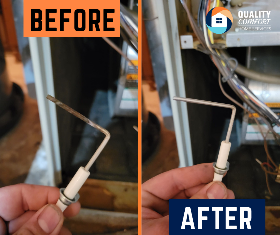
The most prominent feature of a flame sensor is the thin, metallic rod that extends into the path of the burner flame. Usually ranging from two to four inches in length, this rod is typically crafted from high-grade stainless steel or a specialized Kanthal alloy. These materials are chosen for their exceptional resistance to high temperatures and oxidation. Visually, a new sensing rod has a semi-reflective, metallic sheen, though it quickly takes on a matte grey or slightly discolored appearance once it has been subjected to the heat of a furnace.
The Ceramic Insulator
The metal rod is encased in a thick sleeve of white or off-white ceramic. This is the “body” of the sensor. The porcelain or ceramic material serves as a high-temperature dielectric insulator, ensuring that the electrical signal generated by the flame is directed back to the control board rather than grounding out against the furnace chassis. This ceramic portion is usually smooth, cylindrical, and roughly an inch or two long. It is the most fragile part of the assembly; even a hairline crack in this ceramic can cause the sensor to malfunction.
Mounting Brackets and Terminal Connections
At the base of the ceramic insulator, you will find a galvanized steel mounting bracket. This bracket usually features a single hole for a hex-head screw, which secures the sensor to the burner housing. Extending from the opposite end of the ceramic (the side away from the fire) is a single electrical terminal. This is typically a ¼-inch male spade connector, designed to receive the wire leading back to the Integrated Furnace Control (IFC) board. Unlike thermocouples, which often have two wires or a copper lead, a flame sensor almost always utilizes a single-wire connection.
The Technology of Detection: How the Sensor Operates
To understand why a flame sensor looks the way it does, one must understand the “Tech” behind it. The sensor operates on a principle known as flame rectification. This is a sophisticated method of using the flame itself as a component in an electrical circuit.
The Physics of Flame Ionization
When gas burns, the chemical reaction of combustion creates a plasma field full of ionized particles. These ions are capable of conducting electricity. The furnace’s control board sends a low-voltage Alternating Current (AC) to the flame sensor rod. When the flame envelops the rod, the ionized air allows the electricity to jump from the rod, through the flame, to the grounded burner head.
Converting AC to DC (Rectification)
The ingenious part of this technology is the “rectification.” Because the surface area of the burner head is much larger than the surface area of the thin sensor rod, the flame acts as a diode. It allows electricity to flow more easily in one direction than the other, effectively converting the AC signal into a small Direct Current (DC) signal, measured in microamps (µA). If the control board detects this specific DC signal, it “knows” a flame is present and allows the gas valve to remain open. If the signal is absent or too weak, the system shuts down for safety.
Identifying Wear, Tear, and Technological Failure

Because the flame sensor lives in a “hellish” environment of constant thermal expansion and chemical reaction, its physical appearance changes over time. Being able to “read” the visual state of a sensor is a key skill in hardware diagnostics.
Carbon Buildup and Silica Contamination
The most common visual indicator of a failing sensor is the presence of carbon soot or a thin, white coating of silica. While gas is a relatively clean fuel, impurities in the air (such as dust or chemical vapors from laundry detergents stored near the furnace) can burn and deposit a microscopic layer of insulation over the metal rod. Visually, the rod will look “dirty” or “dusty.” This layer is non-conductive, meaning it blocks the flow of ions and prevents the flame rectification process, leading to “short cycling” where the furnace starts for a few seconds and then shuts down.
Oxidation and Pitting
Over years of service, the metal rod may begin to show signs of pitting or heavy oxidation. If the rod looks like it is “flaking” or if the metal appears significantly thinner than it should be, the structural integrity of the sensor has been compromised. This oxidation increases electrical resistance, making it harder for the microamp signal to reach the control board.
Stress Fractures in the Ceramic
Extreme temperature fluctuations (moving from room temperature to over 1,000 degrees Fahrenheit in seconds) can cause the ceramic insulator to develop stress fractures. When inspecting a sensor, it is vital to look for “spider-web” cracks. If moisture or carbon gets into these cracks, the electricity can “leak” to the bracket, bypassing the rod entirely. This is a common cause of phantom ignition failures that are difficult to diagnose without a close visual inspection.
Maintenance and Diagnostic Tools: A Tech Tutorial
If a flame sensor looks dirty, it doesn’t always mean it needs to be replaced. Because it is a solid-state component with no moving parts, it is often restorable through proper maintenance.
The Cleaning Protocol
To clean a flame sensor, tech professionals use a very fine abrasive. It is a common mistake to use heavy-grit sandpaper, which can create deep grooves in the metal that actually encourage faster carbon buildup in the future. Instead, a light rub with a piece of Scotch-Brite pad or high-grit emery cloth is recommended. The goal is to restore the metallic luster of the rod without removing significant amounts of material. After cleaning, it is imperative to wipe the rod with a clean cloth to remove any oils from your skin, as these can bake onto the surface and create new points of failure.
Testing with a Multimeter
Beyond a visual check, the “tech” way to verify a sensor is by using a digital multimeter capable of measuring microamps (µA). By placing the meter in series with the flame sensor wire while the furnace is running, a technician can see the exact strength of the signal. Most modern systems require a signal between 1.5 and 5.0 microamps. If the sensor looks clean but the reading is below 1.0 µA, the sensor or the control board itself may be nearing the end of its functional life.
The Future of Flame Sensing: Beyond the Metal Rod
As we move further into the era of the Smart Home and Industrial Internet of Things (IIoT), flame sensing technology is evolving. While the traditional rod remains the standard for residential furnaces due to its reliability and low cost, new technologies are emerging.
Optical and Ultraviolet (UV) Sensors
In high-end commercial applications and modern high-efficiency boilers, optical flame sensors are becoming more common. These sensors “look” for the specific light spectrum emitted by a flame (ultraviolet or infrared). Unlike the rod, these sensors do not need to sit inside the fire, which eliminates the problem of carbon buildup and oxidation. They are essentially high-speed cameras tuned to a specific frequency.
Integration with Smart Diagnostics
Modern “communicating” HVAC systems now include sensors that can report their own health. Instead of waiting for the furnace to fail, the system’s onboard computer monitors the microamp trend over months. If it sees the signal strength degrading from 4.0 µA to 2.1 µA, it can send an alert to the user’s smartphone or to a central monitoring station, suggesting a cleaning before the system actually breaks down. This shift from reactive to predictive maintenance is a hallmark of current technology trends.
The flame sensor may be small, but it represents a perfect marriage of physics, material science, and safety engineering. Whether you are looking at a classic stainless steel rod or a modern UV scanner, understanding what these components look like—and the high-tech principles that govern them—is essential for anyone interacting with modern thermal systems.
aViewFromTheCave is a participant in the Amazon Services LLC Associates Program, an affiliate advertising program designed to provide a means for sites to earn advertising fees by advertising and linking to Amazon.com. Amazon, the Amazon logo, AmazonSupply, and the AmazonSupply logo are trademarks of Amazon.com, Inc. or its affiliates. As an Amazon Associate we earn affiliate commissions from qualifying purchases.