In the vast and intricate world of electronics, understanding the behavior of fundamental components is paramount to designing, troubleshooting, and innovating. Among the most ubiquitous and critical building blocks are resistors (R) and capacitors (C). When these two are combined, they form an RC circuit, a configuration whose response to voltage changes is characterized by a crucial parameter: the time constant. Far from being an abstract theoretical concept, the time constant (often denoted by the Greek letter tau, τ) is the very heartbeat of many electronic systems, dictating everything from the smoothness of a power supply to the timing precision of a digital clock.
Imagine flicking a light switch; the light appears instantaneously. But what if we needed a light to fade in slowly, or a system to activate after a specific delay? This is where the time-dependent behavior of an RC circuit, governed by its time constant, becomes indispensable. It’s a measure of how quickly an RC circuit can respond to a sudden change in voltage, essentially defining its “memory” or its ability to charge and discharge over time. For engineers, hobbyists, and anyone delving into the nuts and bolts of electrical systems, grasping the time constant is not just beneficial—it’s foundational. It unlocks the door to understanding filters, timers, oscillators, and countless other circuits that power our digital age.
Deciphering the RC Circuit: Resistors, Capacitors, and Their Union
Before we can fully appreciate the time constant, it’s essential to have a clear understanding of the individual players in an RC circuit: the resistor and the capacitor, and how their interaction creates a dynamic, time-sensitive system.
The Resistor’s Role in Current Control
A resistor is perhaps the simplest and most common electronic component. Its primary function, as its name suggests, is to resist the flow of electric current. Governed by Ohm’s Law (V = IR), a resistor creates a voltage drop across itself that is proportional to the current passing through it. In an RC circuit, the resistor is crucial for controlling the rate at which current flows into or out of the capacitor. Without a resistor, a capacitor would charge almost instantaneously (limited only by the internal resistance of the voltage source and wiring), making it difficult to control the timing. By introducing resistance, we can precisely regulate the speed of the charging and discharging processes.
The Capacitor’s Function as an Energy Store
A capacitor, in contrast to a resistor, is an energy storage device. It stores electrical energy in an electric field between two conductive plates separated by an insulating dielectric material. When a voltage is applied across a capacitor, it accumulates charge, and this charge accumulation builds up a corresponding voltage across its plates. Crucially, a capacitor resists sudden changes in voltage. It acts like a small, temporary battery, absorbing current when voltage increases and releasing current when voltage decreases. The amount of charge a capacitor can store for a given voltage is defined by its capacitance (C), measured in Farads (F).
The Synergistic Relationship in an RC Circuit
When a resistor and a capacitor are connected in series, they form the most basic RC circuit. The resistor acts as a gatekeeper, controlling the pace at which the capacitor charges or discharges.
Consider an uncharged capacitor connected in series with a resistor to a DC voltage source. When the switch is closed, current immediately starts to flow through the resistor and into the capacitor. Initially, the capacitor acts almost like a short circuit because it has no stored charge and thus no voltage across it. As current flows, charge builds up on the capacitor plates, and the voltage across the capacitor begins to rise. This rising capacitor voltage opposes the source voltage, causing the current flowing through the resistor to decrease. This process continues until the capacitor is fully charged, at which point the voltage across it equals the source voltage, and the current flow effectively stops.
This gradual, time-dependent charging (and similarly, discharging) process is the direct result of the resistor limiting the current and the capacitor storing charge. The time constant quantifies just how “gradual” or “rapid” this process will be.
Understanding the Time Constant (τ): The Heart of RC Dynamics
The time constant (τ) is the single most important parameter describing the transient response of an RC circuit. It defines the characteristic time scale over which the voltage across the capacitor changes in response to a step change in input voltage.
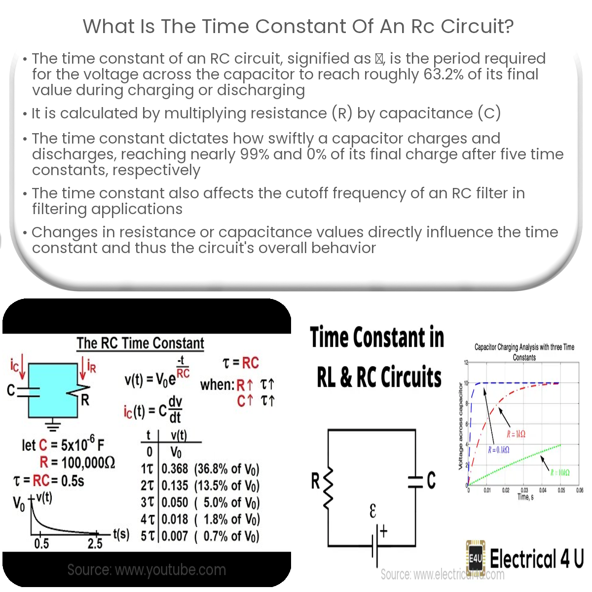
Mathematical Definition and Significance (τ = RC)
The time constant τ for a simple series RC circuit is calculated by the product of the resistance (R) and the capacitance (C):
τ = R * C
Where:
- τ (tau) is the time constant, measured in seconds.
- R is the resistance, measured in Ohms (Ω).
- C is the capacitance, measured in Farads (F).
The unit analysis is revealing: Ohms * Farads = (Volts/Amps) * (Coulombs/Volts) = Coulombs/Amps = Coulombs/(Coulombs/Seconds) = Seconds. This confirms that τ indeed represents a duration.
The significance of this simple formula is profound. It tells us that a larger resistance will slow down the charging/discharging process because it limits the current more severely. Similarly, a larger capacitance will also slow down the process because it requires more charge to reach the same voltage, and thus takes longer to fill up or empty.
The Concept of Exponential Charge and Discharge
The charging and discharging of a capacitor in an RC circuit do not happen linearly; instead, they follow an exponential curve.
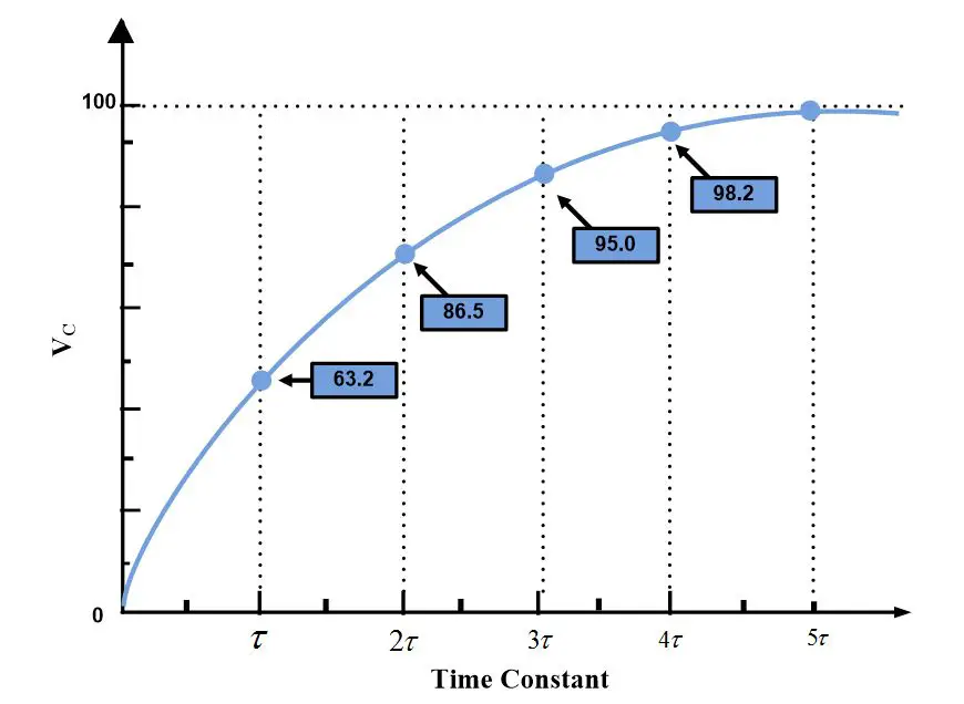
- During Charging: When a DC voltage is applied, the voltage across the capacitor rises exponentially towards the source voltage. After one time constant (1τ), the capacitor will have charged to approximately 63.2% of the final source voltage. After two time constants (2τ), it reaches about 86.5%, after 3τ, 95%, after 4τ, 98.2%, and after 5τ, it is considered fully charged (over 99%).
- During Discharging: If a charged capacitor is allowed to discharge through a resistor, its voltage drops exponentially towards zero. After one time constant (1τ), the voltage across the capacitor will have fallen to approximately 36.8% of its initial voltage. After 5τ, it is considered fully discharged.
This exponential behavior is fundamental. It means that the capacitor charges or discharges most rapidly at the beginning of the process when the voltage difference is largest, and the rate of change slows down as it approaches its final state.
Visualizing τ: Graphical Representation
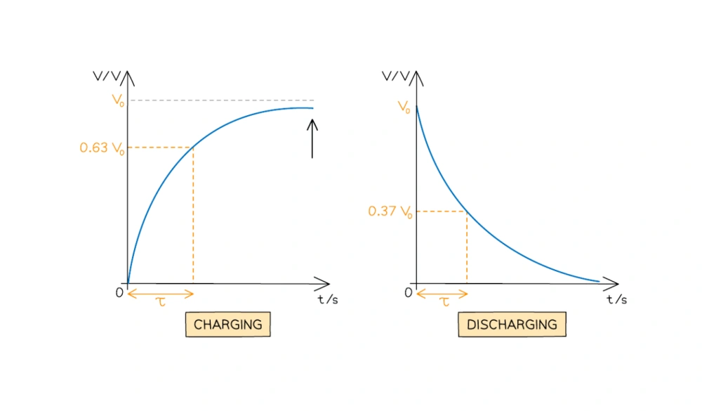
Plotting the voltage across a capacitor against time reveals the exponential nature clearly. For a charging capacitor, the graph starts at 0V and curves upwards, flattening out as it approaches the source voltage. The point on this curve where the voltage reaches 63.2% of the final value corresponds to exactly one time constant (τ) on the time axis. Conversely, for a discharging capacitor, the graph starts at the initial voltage and curves downwards, gradually approaching 0V. The point where it drops to 36.8% of its initial value also marks one time constant. These graphs are invaluable tools for understanding and predicting RC circuit behavior.
Practical Implications and Applications of the Time Constant
The time constant isn’t just a theoretical number; it’s a critical design parameter that dictates the performance of countless electronic circuits. Its manipulation allows engineers to tailor the response of systems to specific needs.
Filtering and Signal Conditioning
One of the most common applications of RC circuits is in filtering. An RC filter can act as a low-pass filter, allowing low-frequency signals to pass through while attenuating (blocking) high-frequency signals. The time constant determines the cutoff frequency (f_c) of such a filter, which is the frequency at which the output power is half of the input power (or voltage is 70.7% of the input voltage). The relationship is given by:
f_c = 1 / (2πRC) = 1 / (2πτ)
By selecting appropriate R and C values, engineers can design filters to remove unwanted noise from signals, smooth out fluctuating voltages, or separate different frequency components of a complex signal.
Timing Circuits and Oscillators
The time-dependent charging and discharging of capacitors are the backbone of many timing circuits. Components like the ubiquitous 555 timer IC leverage RC circuits to generate precise time delays, pulse widths, or oscillation frequencies. In a monostable multivibrator, the time constant determines the duration of the output pulse. In an astable multivibrator (oscillator), it determines the frequency of the repetitive square wave output. From traffic light controllers to internal clock signals in microcontrollers, RC timing is everywhere.
Debouncing Switches and Data Acquisition
Mechanical switches (like pushbuttons) don’t make a clean, instantaneous contact when pressed. Instead, they “bounce” several times, creating multiple rapid on/off transitions before settling. To a fast digital circuit, these bounces can be interpreted as multiple presses. An RC circuit can “debounce” a switch by slowing down the voltage change seen by the digital input, effectively ignoring the rapid, short-duration bounces and registering only the sustained press. Similarly, in data acquisition systems, RC circuits are used to integrate signals over time or to provide anti-aliasing filtering before analog-to-digital conversion.
Power Supply Ripple Filtering
After AC voltage is rectified into DC, it often contains a ripple—small, unwanted AC variations superimposed on the DC output. A large capacitor (often in conjunction with a resistor or inductor) in a power supply acts as a filter, storing charge when the rectified voltage is high and discharging it slowly through the load when the voltage dips. The time constant of this RC combination (load resistance R_L and filter capacitance C) determines how effectively the capacitor can smooth out this ripple, ensuring a stable DC output for electronic devices.
Calculating and Measuring the Time Constant
Understanding how to calculate and, more importantly, measure the time constant is crucial for both theoretical understanding and practical circuit design and debugging.
Step-by-Step Calculation
Calculating the time constant is straightforward given the resistance and capacitance values:
Example:
Suppose you have an RC circuit with a resistor R = 10 kΩ (10,000 Ohms) and a capacitor C = 1 μF (0.000001 Farads).
- Convert units to base SI units if necessary: R is already in Ohms, C needs to be in Farads.
R = 10,000 Ω
C = 1 * 10^-6 F - Apply the formula τ = RC:
τ = (10,000 Ω) * (1 * 10^-6 F)
τ = 0.01 seconds
So, for this circuit, the time constant is 10 milliseconds. This means that if we apply a 5V source, the capacitor will charge to approximately 3.16V (63.2% of 5V) in 10 milliseconds.
Experimental Measurement Techniques
While calculation provides a theoretical value, real-world components have tolerances, and parasitic elements can influence behavior. Experimental measurement is vital for verification.
- Oscilloscope Method: This is the most accurate way.
- Set up the RC circuit with a square wave input from a function generator. The square wave acts as a repetitive ON/OFF switch, allowing you to observe both charging and discharging. The frequency of the square wave should be significantly slower than 1/(5τ) to allow the capacitor to fully charge and discharge.
- Connect the oscilloscope probes across the capacitor.
- Observe the waveform on the oscilloscope screen. It will show exponential charging and discharging curves.
- Measure the time it takes for the capacitor voltage to reach 63.2% of its final value (during charging) or drop to 36.8% of its initial value (during discharging). This measured time is your experimental time constant.
- Multimeter Method (Indirect): You can measure the actual resistance and capacitance values of your components using a multimeter (if it has R and C measurement capabilities) and then calculate τ. This is less direct for verifying the circuit’s dynamic behavior but useful for checking component integrity.
Beyond the Basics: Advanced Considerations
While the fundamental τ = RC formula holds for simple series circuits, more complex scenarios introduce additional factors that influence the time constant and overall circuit behavior.
Series vs. Parallel RC Circuits
The formula τ = RC typically applies to a series RC circuit where the capacitor charges or discharges through a single resistor. In more complex circuits, you might have multiple resistors or capacitors. To find the effective time constant:
- Find the Thevenin equivalent resistance (R_Th) seen by the capacitor. This is the total resistance that the capacitor “sees” during its charging/discharging path.
- If multiple capacitors exist: Simplify them into an equivalent capacitance (Ceq). For capacitors in parallel, Ceq = C1 + C2 + …; for capacitors in series, 1/Ceq = 1/C1 + 1/C2 + …
Once RTh and Ceq are determined, the time constant remains τ = RTh * C_eq.
Non-Ideal Components and Real-World Scenarios
Ideal components are theoretical constructs. Real-world resistors have tolerances (e.g., ±5%), and their resistance can vary with temperature. Capacitors are even more complex:
- Equivalent Series Resistance (ESR): Every capacitor has a small internal resistance in series with its capacitance. This ESR can affect high-frequency performance and lead to power dissipation.
- Equivalent Series Inductance (ESL): At very high frequencies, the leads and internal structure of a capacitor can exhibit parasitic inductance, turning the capacitor into an RLC circuit.
- Leakage Current: No capacitor is a perfect insulator; a tiny leakage current flows through the dielectric, causing a very slow discharge over time.
These non-idealities can subtly alter the effective time constant and limit the performance of circuits, especially at extreme frequencies or temperatures.
Impact of Frequency on RC Circuit Behavior
The time constant is intrinsically linked to the frequency response of an RC circuit. For a low-pass filter, a small time constant (τ) means a higher cutoff frequency, allowing more high-frequency signals to pass. Conversely, a large time constant means a lower cutoff frequency, making the filter more effective at blocking high frequencies. This relationship is critical for applications like audio equalizers, RF filters, and analog-to-digital converter pre-filters, where precise frequency shaping is required. The interplay between R, C, and the operating frequency fundamentally determines how the circuit interacts with alternating current (AC) signals.
Conclusion
The time constant of an RC circuit, a seemingly simple product of resistance and capacitance, is a cornerstone concept in electronics. It quantifies the dynamic behavior of these fundamental circuits, dictating the speed at which they respond to changes in voltage. From smoothing power supplies and debouncing switches to creating precise timing circuits and filtering unwanted signals, the time constant is not merely a theoretical value but a practical design parameter that shapes the functionality of virtually every electronic device around us.
Mastering the concept of τ provides a deep insight into how circuits operate over time, enabling engineers and enthusiasts to predict performance, troubleshoot issues, and innovate new solutions. As technology continues to advance, demanding ever more precise timing and signal conditioning, the foundational understanding of the RC time constant remains as relevant and indispensable as ever. It is the invisible force that orchestrates the rhythm of our electronic world, ensuring that signals arrive on time, data is clean, and devices operate with predictable precision.
aViewFromTheCave is a participant in the Amazon Services LLC Associates Program, an affiliate advertising program designed to provide a means for sites to earn advertising fees by advertising and linking to Amazon.com. Amazon, the Amazon logo, AmazonSupply, and the AmazonSupply logo are trademarks of Amazon.com, Inc. or its affiliates. As an Amazon Associate we earn affiliate commissions from qualifying purchases.