The transition toward sustainable transportation is not merely a shift in fuel sources but a fundamental evolution in how we interact with technology and infrastructure. At the heart of this evolution for Tesla owners is the Tesla Wall Connector—a sophisticated piece of hardware designed to bridge the gap between the municipal electrical grid and the advanced battery management systems of a modern electric vehicle (EV). Installing a Tesla Wall Connector is more than a simple home improvement project; it is a technical deployment that requires an understanding of electrical engineering, hardware configuration, and software integration.

This guide provides an in-depth technical analysis and step-by-step walkthrough for installing the Tesla Wall Connector (Gen 3), focusing on the hardware specifications, installation protocols, and the digital commissioning process required to optimize your charging ecosystem.
Technical Specifications and Infrastructure Requirements
Before the physical installation begins, a thorough assessment of the existing electrical infrastructure is mandatory. The Tesla Wall Connector is a high-power device capable of delivering up to 11.5 kW of power, which necessitates a dedicated circuit and careful consideration of load capacity.
Electrical Capacity and Circuit Breaker Sizing
The Gen 3 Wall Connector is designed for flexibility, allowing it to be installed on various circuit breaker sizes ranging from 15 amps to 60 amps. However, to achieve the maximum charging speed of 48 amps, a 60-amp circuit breaker must be installed. This follows the “80% rule” in electrical engineering, where a continuous load should not exceed 80% of the circuit breaker’s rated capacity.
When selecting a breaker, ensure it is a high-quality, dual-pole breaker compatible with your electrical panel. It is important to note that the Wall Connector includes integrated GFCI (Ground Fault Circuit Interrupter) protection. Therefore, installing a GFCI circuit breaker at the panel is generally unnecessary and can lead to “nuisance tripping,” where the two GFCI systems interfere with one another.
Wire Gauge and Conduit Selection
Choosing the correct wire gauge is critical for safety and efficiency. For a 60-amp installation, most technical standards recommend 6 AWG copper wire. However, if the run between the electrical panel and the installation site is exceptionally long, a thicker 4 AWG wire may be necessary to mitigate voltage drop.
Technicians must also decide between hard-wiring through the rear or bottom of the unit. The use of high-quality liquid-tight flexible conduit or rigid metal conduit (RMT) is recommended to protect the conductors from environmental factors and physical damage, ensuring the longevity of the installation.
Step-by-Step Installation Protocol
The physical installation of the Tesla Wall Connector involves precise mechanical mounting and secure electrical terminations. Failure to follow these technical steps can result in overheating or hardware failure.
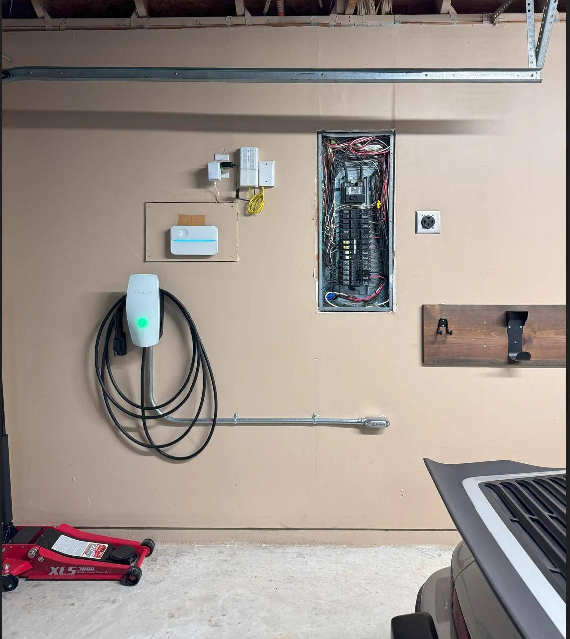
Mounting the Wall Connector
The first step is identifying a suitable mounting location. Ideally, the charger should be placed near the vehicle’s charge port, typically at a height of about 4 feet (1.2 meters) to ensure ergonomic ease of use.
- Template Alignment: Use the provided mounting template to mark the pilot holes. Ensure the unit is perfectly level using a spirit level.
- Structural Integrity: If mounting on drywall, ensure at least two of the mounting screws are anchored directly into a wooden stud. For masonry or concrete, use appropriate wall anchors to ensure the unit can support the weight of the 18-foot or 24-foot charging cable.
- Bracket Attachment: Secure the wirebox (the rear portion of the connector) to the wall. This component serves as the terminal point for the electrical supply.
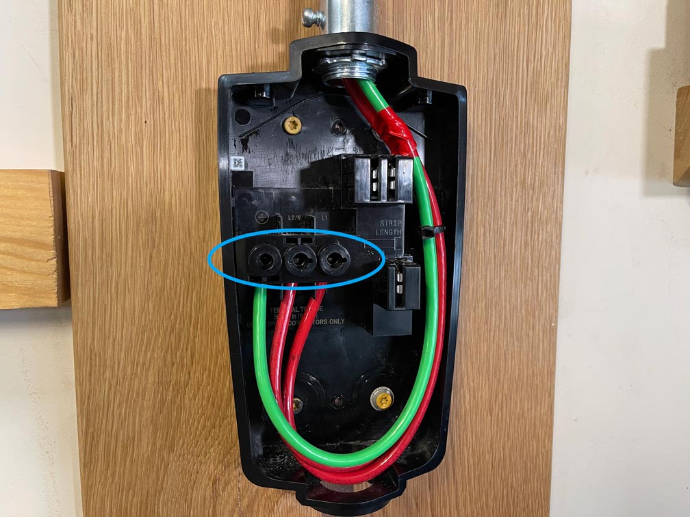
Wiring and Grounding Procedures
Once the wirebox is mounted, the electrical conductors must be landed. This is perhaps the most technical phase of the installation.
- Stripping and Insertion: Carefully strip the insulation from the two hot leads (Lines 1 and 2) and the ground wire. Tesla utilizes high-quality terminal blocks that require specific torque settings.
- Torque Specifications: Using a torque screwdriver, tighten the terminal screws to the manufacturer-specified levels (typically around 50 lb-in or 5.6 Nm). Loose connections are the leading cause of thermal incidents in high-current devices; a secure, torqued connection is non-negotiable.
- Sealing the Unit: Once the wires are secured, the main body of the Wall Connector is snapped onto the wirebox. Ensure the peripheral seal is seated correctly to maintain the unit’s NEMA 3R rating, which protects against rain, sleet, and snow.
Configuring the Software and Connectivity
Unlike traditional chargers, the Tesla Gen 3 Wall Connector is an IoT (Internet of Things) device. It requires a digital commissioning process to function correctly and receive over-the-air (OTA) firmware updates.
Accessing the Commissioning Wizard
After the breaker is flipped on, the Wall Connector will broadcast its own internal Wi-Fi signal. To configure the device:
- Connecting to the SSID: Use a smartphone or laptop to find the Wi-Fi network named “TeslaWallConnector_XXXXXX.” You will need the WPA2 password found on the Quick Start guide or the side of the unit.
- The Captive Portal: Once connected, navigate to
192.168.92.1in a web browser. This opens the internal configuration page. - Setting Circuit Limits: Within the portal, you must specify the breaker size (e.g., 60A). This tells the software the maximum current it is allowed to draw, ensuring the vehicle never pulls more power than the infrastructure can handle.
Integrating with the Tesla App and Wi-Fi Setup
To enable smart features, the Wall Connector must be connected to your home’s 2.4 GHz Wi-Fi network.
- Network Configuration: In the commissioning wizard, select your home Wi-Fi and enter the credentials.
- Firmware Updates: Once connected to the internet, the Wall Connector will automatically check for and download the latest firmware. These updates often include optimizations for charging efficiency and compatibility with new Tesla vehicle models.
- Tesla App Registration: By logging into your Tesla account and scanning the QR code on the device, you can monitor your charging sessions, view historical energy usage data, and manage access control directly from your mobile device.
Optimizing Performance and Troubleshooting
A successful installation is followed by optimization and a clear understanding of the device’s diagnostic signals. This ensures long-term reliability and the ability to scale your charging needs.
Dynamic Power Sharing for Multi-Device Environments
For households with multiple electric vehicles, Tesla offers a sophisticated “Power Sharing” feature. This allows up to six Wall Connectors to share power from a single electrical circuit.
This is a software-driven solution where the chargers communicate via Wi-Fi to dynamically allocate current. If one car is charging, it receives the full available power. If a second car is plugged in, the Wall Connectors automatically negotiate and split the current to prevent overloading the circuit breaker. This represents a significant advancement in home energy management technology, eliminating the need for expensive service upgrades in multi-EV homes.
Diagnostic LED Indicators and Error Codes
The Wall Connector features a vertical LED strip that serves as a diagnostic interface. Understanding these light patterns is essential for technical troubleshooting:
- Solid Green: The unit is powered on and ready to charge.
- Streaming Green: The vehicle is currently charging.
- Solid Red: A hardware fault has occurred. The number of red blinks provides a specific error code (e.g., one blink indicates a ground fault, while three blinks indicate high temperature).
- Blue Pulsing: The Wall Connector is in commissioning mode or waiting for a software update.
In the event of a red light error, the first step is usually a “soft reset” via the button on the side of the charging handle or a “hard reset” by cycling the circuit breaker. If the fault persists, the internal logs accessible via the commissioning portal can provide deeper insights for professional technicians.
Conclusion
Installing a Tesla Wall Connector is a rigorous technical task that transforms a standard residence into a high-performance fueling station. By strictly adhering to electrical codes, precise hardware installation protocols, and thorough software commissioning, users can ensure a seamless and safe charging experience. As EV technology continues to advance, the ability to manage and maintain this localized infrastructure becomes a vital skill set for the modern tech-integrated household. Through proper installation, the Wall Connector provides not just power, but the data and connectivity necessary to optimize the future of personal transportation.
aViewFromTheCave is a participant in the Amazon Services LLC Associates Program, an affiliate advertising program designed to provide a means for sites to earn advertising fees by advertising and linking to Amazon.com. Amazon, the Amazon logo, AmazonSupply, and the AmazonSupply logo are trademarks of Amazon.com, Inc. or its affiliates. As an Amazon Associate we earn affiliate commissions from qualifying purchases.