For enthusiasts of turbocharged or supercharged vehicles, a boost gauge is more than just another accessory; it’s a vital instrument providing a real-time window into the heart of your engine’s performance. Understanding and monitoring boost pressure is crucial for maximizing horsepower, ensuring engine health, and fine-tuning your vehicle’s capabilities. This comprehensive guide will walk you through the entire process of installing a boost gauge, transforming your driving experience with invaluable data at your fingertips.
In the realm of automotive technology, where every modification can unlock new potential, installing a boost gauge stands out as a fundamental upgrade for any forced-induction vehicle. It’s a project that combines practical mechanical skills with a touch of electrical savvy, perfectly aligning with the “Tech” focus of our platform, particularly in the areas of gadgets, tutorials, and digital security (understanding your engine’s limits). While the installation might seem daunting to a novice, with the right preparation, tools, and a clear step-by-step approach, it’s a highly rewarding DIY endeavor that offers tangible benefits to your vehicle’s longevity and performance.
Understanding Your Boost Gauge and Its Purpose
Before diving into the installation process, it’s essential to grasp what a boost gauge does, why it’s indispensable, and the different types available on the market. This foundational knowledge will empower you to make informed decisions throughout your installation.
Why Monitor Boost Pressure?
At its core, a boost gauge measures the manifold absolute pressure (MAP) beyond atmospheric pressure, indicating how much extra air is being forced into your engine by a turbocharger or supercharger. This “boost” directly correlates with the power output of your engine. Monitoring boost pressure serves several critical functions:
- Performance Optimization: For those running aftermarket tunes or modifying their turbos, a boost gauge helps you verify that your engine is achieving the desired boost levels as programmed. It allows you to confirm that performance gains are being realized and helps identify any discrepancies.
- Engine Health and Safety: Excessively high boost pressure can lead to dangerous conditions like pre-ignition or detonation, which can severely damage engine components. A boost gauge acts as an early warning system, alerting you to over-boosting before catastrophic failure occurs. Conversely, a lack of boost can indicate issues like vacuum leaks, wastegate malfunctions, or a failing turbocharger, prompting timely investigation and repair.
- Driving Feedback: For performance driving, the gauge provides immediate feedback on how your engine is responding to throttle input. It allows you to modulate boost precisely, optimizing acceleration and ensuring smoother power delivery.
- Troubleshooting: When diagnosing engine issues, especially those related to power delivery, the boost gauge is an invaluable tool. Abnormal readings can quickly point towards a problem in the forced induction system, saving time and money on diagnostics.
Types of Boost Gauges: Mechanical vs. Electrical
The market offers two primary types of boost gauges, each with its own set of advantages and considerations:
- Mechanical Boost Gauges: These gauges connect directly to the engine’s intake manifold via a vacuum line. The manifold pressure physically moves a needle on the gauge face.
- Pros: Generally less expensive, offer extremely accurate and instantaneous readings, require no electrical wiring for sensor input (though some may need power for illumination).
- Cons: Require running a vacuum line through the firewall into the cabin, which can be challenging and introduces a potential point of failure (leak) within the vehicle’s vacuum system. The line can also transmit engine noise or fluids if not properly installed.
- Electrical Boost Gauges: These gauges use an electronic pressure sensor (MAP sensor) installed in the engine bay to measure boost. The sensor converts the pressure reading into an electrical signal, which is then transmitted via wiring to the gauge inside the cabin.
- Pros: Cleaner cabin installation as only electrical wires (not a vacuum line) need to be routed through the firewall. Less prone to cabin leaks or engine noise transmission. Often come with advanced features like peak recall, warning lights, and dimmer control.
- Cons: Typically more expensive due to the sensor and associated electronics. Readings can have a very slight delay compared to mechanical gauges, though modern electrical gauges are incredibly fast. Requires more electrical wiring for both the sensor and the gauge itself.
Decision Factors: Your choice will depend on your budget, comfort level with wiring versus vacuum line routing, and desired features. For absolute purists seeking raw, unadulterated feedback, mechanical gauges are often preferred. For a cleaner install with more features, electrical gauges are a strong contender. Regardless of your choice, the core principles of connecting to a boost source and providing power/mounting remain similar.
Essential Tools and Materials
Before beginning the installation, gather all necessary tools and materials. Having everything ready will streamline the process and prevent frustrating interruptions.
Common Tools:
- Basic Hand Tools: Screwdriver set (Phillips and flathead), socket set, wrench set.
- Wire Strippers and Crimpers (for electrical gauges).
- Multimeter (for electrical gauges, to test power/ground).
- Drill and Drill Bits (for mounting the gauge pod, routing lines/wires).
- Utility Knife or Box Cutter.
- Zip Ties/Cable Ties.
- Electrical Tape.
- Heat Shrink Tubing and Heat Gun (for professional electrical connections).
- Panel Removal Tools (plastic pry tools to safely remove interior trim).
- Safety Glasses and Gloves.
Materials (may vary based on gauge type):
- Boost Gauge Kit: Includes the gauge, sending unit (for electrical), vacuum line/harness, T-fitting.
- Gauge Pod or Mounting Cup: To secure the gauge in your desired location (A-pillar, dashboard, vent mount).
- Additional Vacuum Line (if included line is too short or for routing flexibility, typically silicone or rubber with appropriate diameter).
- Vacuum T-Fitting (if not included or if you need a different size/material).
- Grommets (to protect lines/wires passing through the firewall).
- Add-a-Circuit Fuse Tap (for safe power sourcing from the fuse box).
- Ring Terminals/Spade Connectors (for electrical connections).
- Thread Sealant or Teflon Tape (for NPT fittings on mechanical gauges/sensors).
- Wire Loom or Convoluted Tubing (to protect exposed wires/lines in the engine bay).
Pre-Installation Planning and Safety
A successful installation begins with meticulous planning and adherence to safety protocols. Rushing through these initial steps can lead to frustration, damage, or even injury.
Safety First: Disconnecting the Battery
Crucial Step: Whenever performing electrical work or working near sensitive engine components, always disconnect the vehicle’s negative battery terminal first. This prevents accidental short circuits, electrical fires, and potential damage to your vehicle’s ECU or other electronic systems. Use a wrench to loosen the negative terminal clamp and set it aside, ensuring it cannot accidentally reconnect.
Choosing the Right Location for Your Gauge
The placement of your boost gauge is a balance between visibility, accessibility, and aesthetics. Consider these popular options:
- A-Pillar Mount: One of the most popular choices. Gauge pods attach to the A-pillar (the pillar next to the windshield). This offers an almost line-of-sight view without significantly obstructing your driving view. Many aftermarket options are specifically designed for various vehicle models.
- Dashboard Mount: Using a universal pod, the gauge can be mounted on top of the dashboard. Ensure it doesn’t obstruct visibility or airbag deployment areas.
- Vent Mount: Some kits integrate the gauge into an existing air vent, offering a very clean, factory-like look. This might sacrifice some airflow from that particular vent.
- Steering Column Mount: Attaches to the steering column, often just above or to the side of the instrument cluster.
- Center Console/Radio Bezel Mount: Requires more custom fabrication but can achieve a very integrated look, especially in older vehicles.
Considerations:
- Driver Visibility: The gauge should be easily readable without taking your eyes too far off the road.
- Airbag Clearance: Ensure the gauge or its mounting pod does not interfere with the deployment path of any airbags.
- Cable Routing: Plan how you will route the vacuum line or electrical wires from the engine bay to your chosen cabin location, minimizing visible wires.
- Aesthetics: Choose a location that complements your vehicle’s interior.
Identifying a Suitable Vacuum/Boost Source
This is perhaps the most critical mechanical aspect of the installation. A proper boost source ensures accurate readings.
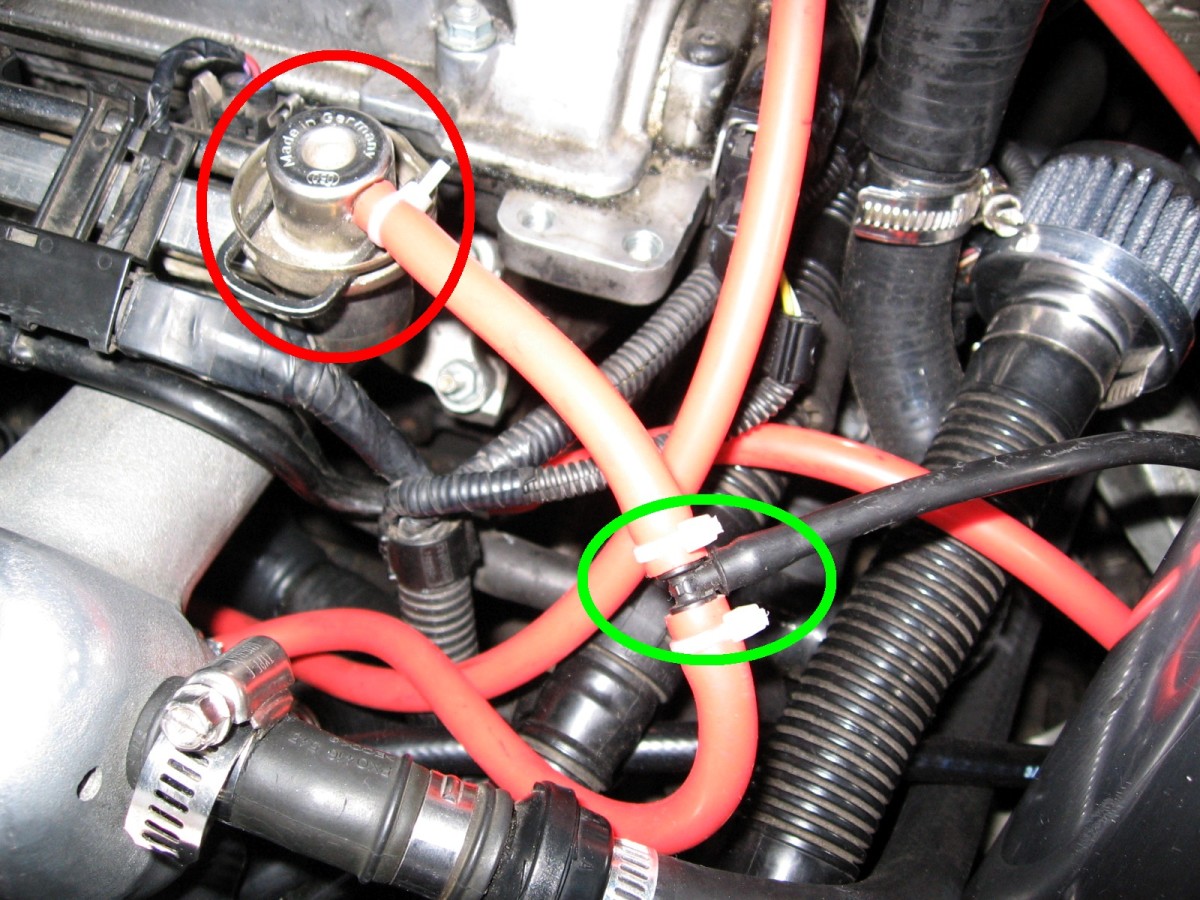
- Intake Manifold: The most common and reliable location. You’ll need to find a vacuum port on the intake manifold that is exposed to both vacuum (when off-throttle) and boost (under acceleration). Many vehicles have spare capped ports or ports used for less critical systems that can be “T-ed” into.
- Brake Booster Line: This is often a large vacuum line leading to the brake booster. While accessible, tapping into this line is generally not recommended as it can potentially affect brake performance if a leak develops.
- Fuel Pressure Regulator (FPR) Line: If your vehicle has a vacuum-referenced FPR, this line is an excellent, accurate source.
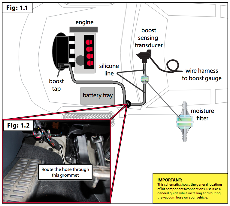
- Dedicated Boost Tap: Some aftermarket kits offer specific boost taps that install directly into the intake manifold or charge pipes, providing a clean and reliable source without splicing existing lines.
Verification: Once you’ve identified a potential port, ensure it provides both vacuum (at idle) and boost (under acceleration). You can test this using a simple vacuum gauge or by carefully observing a temporary connection. Always ensure your chosen source is after the throttle body for the most accurate manifold pressure readings. For electrical gauges, the sensor will be installed at this boost source, usually requiring a small manifold tap or a specific adapter.
Step-by-Step Boost Gauge Installation
With planning complete and tools ready, it’s time to begin the physical installation. We’ll outline the general steps, noting variations for mechanical and electrical gauges.
Mounting the Boost Gauge
- Prepare the Mounting Location: If using an A-pillar pod, remove the existing A-pillar trim. For dash mounts, clean the surface where the pod will adhere.
- Secure the Gauge in the Pod: Most pods have a rubber ring or retainer that holds the gauge snugly. Insert the gauge into its pod/cup.
- Mount the Pod:
- A-Pillar: Depending on the design, the pod might clip onto the existing pillar, or you might need to drill small holes for screws to secure it. If drilling, measure carefully and use painter’s tape to prevent scratches.
- Dashboard: Use strong double-sided automotive adhesive tape or screws (if comfortable drilling into your dash).
- Vent Mount: Follow the specific instructions for your vent-mounted kit.
- Route Lines/Wires from Gauge: Once the gauge is mounted, gently route the vacuum line (mechanical) or electrical harness (electrical) from the back of the gauge, down behind the trim, and towards the firewall.
Running the Vacuum Line (Mechanical Gauge) or Wiring Harness (Electrical Gauge)
This step involves getting the signal (vacuum or electrical) from the engine bay to the cabin.
- Locate a Firewall Pass-Through: Identify an existing grommet in the firewall (e.g., for the main wiring harness, hood release cable, or clutch line) that you can safely puncture or use. Alternatively, you may need to drill a new hole.
- Warning: Be extremely careful when drilling through the firewall. Ensure you know what’s on the other side to avoid drilling into existing wiring, brake lines, or fuel lines. Start with a small pilot hole, then enlarge it.
- Pass the Line/Wires:
- Mechanical Gauge: Push the vacuum line through the grommet/hole from the engine bay into the cabin. Ensure you have enough slack on both ends.
- Electrical Gauge: Push the wiring harness (for the sensor) through the grommet/hole. The main gauge power/ground/illumination wires will also pass through, but usually, these originate from inside the cabin, so you might feed them the other way or pass them through a different route.
- Protect the Line/Wires: Use a new, properly sized grommet if you drilled a new hole. For existing grommets, apply RTV silicone sealant around the line/wires to prevent water leaks and provide additional insulation.
- Route in Engine Bay: Route the vacuum line or sensor wiring carefully away from hot engine components (exhaust manifolds, turbochargers) and moving parts (belts, pulleys). Use zip ties to secure it along existing harnesses or frame rails. Use wire loom or convoluted tubing for added protection against heat and abrasion.
- Route in Cabin: Continue routing the line/wires from the firewall to your mounted gauge, tucking them neatly behind trim panels, under the carpet, or along the existing wiring harnesses to keep the interior clean and safe.
Connecting to the Vacuum/Boost Source
This is where the gauge connects to the engine’s pressure system.
- For Mechanical Gauges:
- Identify the Boost Source: Revisit the chosen vacuum port on the intake manifold.
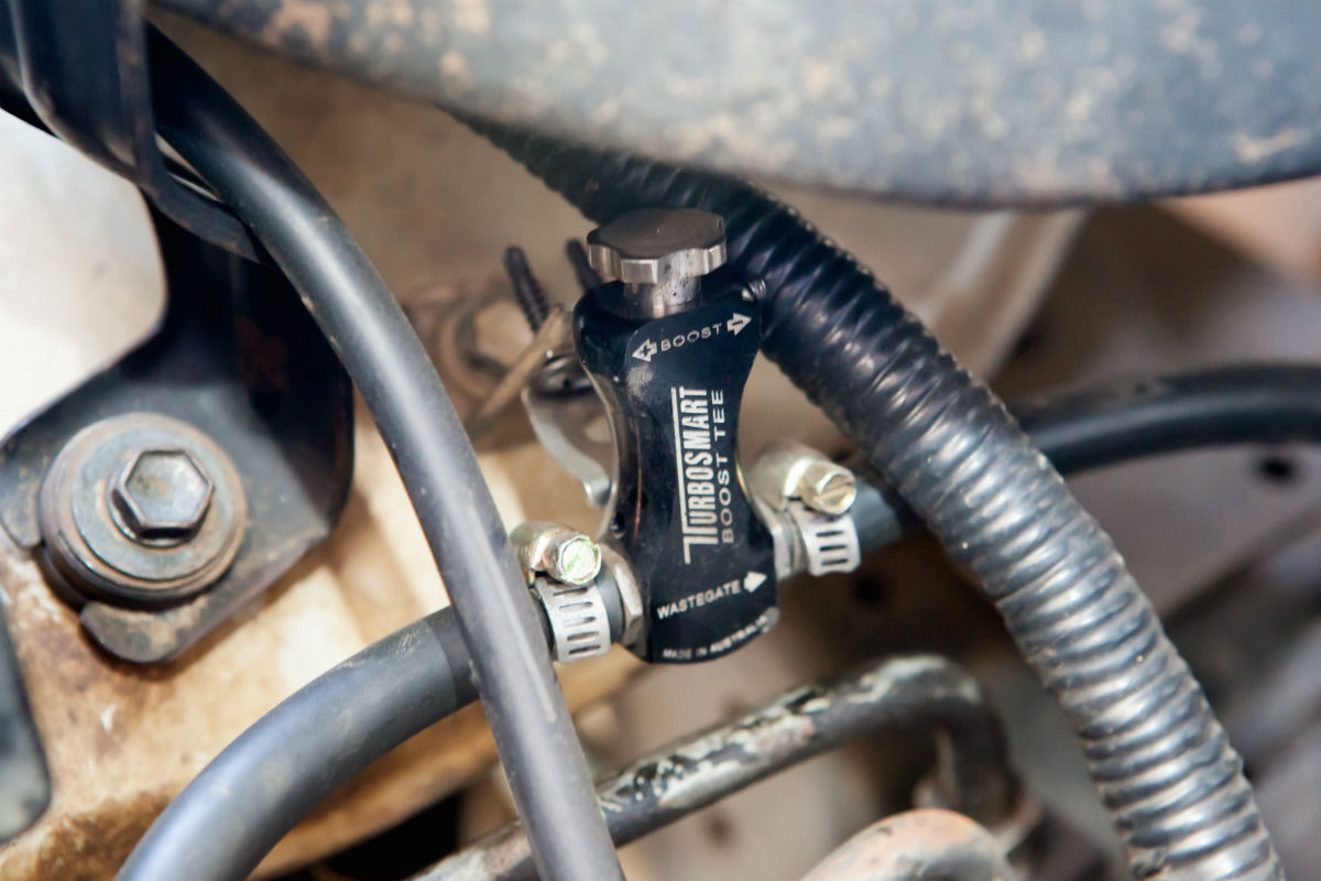
- Install the T-Fitting: Cut an appropriate section of the existing vacuum line (if tapping into one) and insert the T-fitting. Ensure a snug fit.
- Connect Gauge Line: Attach one end of your routed vacuum line from the gauge to the open leg of the T-fitting.
- Secure and Seal: Use small hose clamps or zip ties on all connections to prevent vacuum/boost leaks. For NPT threaded ports, use thread sealant or Teflon tape.
- For Electrical Gauges (Sensor Installation):
- Install the Boost Sensor: The electronic boost sensor needs to be installed at the boost source. This might involve replacing an existing MAP sensor (if compatible), using a dedicated boost tap adapter, or screwing the sensor into a spare threaded port on the intake manifold.
- Connect Vacuum Line (if applicable): Some electrical sensors still use a short vacuum line to connect to the boost source. Follow the sensor’s specific instructions.
- Wire the Sensor: Connect the sensor’s wiring harness to the main gauge wiring, following the color codes provided by the manufacturer. Secure these connections with crimps and heat shrink tubing for reliability.
- Mount the Sensor: Secure the sensor in the engine bay away from extreme heat and vibrations, using zip ties or a small bracket.
Wiring for Power, Ground, and Illumination (Electrical Gauge)
This step is primarily for electrical gauges, but even mechanical gauges usually require power for backlighting.
- Power (Switched 12V):
- Locate a Switched Power Source: This is a circuit that receives power only when the ignition is on (or in the accessory position). The fuse box inside the cabin is usually the best place.
- Use an Add-a-Circuit Fuse Tap: This device allows you to safely tap into an existing fuse slot without cutting into factory wiring. Find a fuse that powers something non-critical (e.g., radio, cigarette lighter, accessory socket) and that is switched.
- Connect: Insert the original fuse and a new fuse (for the gauge) into the add-a-circuit, then plug it into the fuse box. Connect the gauge’s power wire to the add-a-circuit’s wire.
- Ground:
- Locate a Chassis Ground: Find a clean, unpainted metal bolt or screw directly attached to the vehicle’s chassis, typically behind interior panels.
- Connect: Use a ring terminal on the gauge’s ground wire and secure it tightly to the chassis ground point. Ensure good metal-to-metal contact for a reliable ground.
- Illumination (Optional):
- Locate a Dimmer Circuit: This wire receives power when the headlights/parking lights are on and dims with the dash lights. Often found behind the stereo, headlight switch, or another dash light.
- Tap In: Carefully identify the correct wire using your multimeter (it should show 12V when lights are on and vary with the dimmer switch). Use a T-tap connector or carefully splice into this wire.
- Connect: Connect the gauge’s illumination wire to this tapped source.
Securing and Tidying Up
Once all connections are made, it’s time for the final touches.
- Secure All Lines and Wires: Use zip ties generously in both the engine bay and cabin to prevent lines/wires from dangling, rubbing, or interfering with moving parts. This is crucial for safety and longevity.
- Reinstall Trim Panels: Carefully reattach any interior trim panels that were removed. Ensure all clips and screws are properly seated.
- Double-Check Connections: Briefly review all mechanical and electrical connections to ensure they are secure and properly insulated.
Post-Installation Testing and Calibration
The installation isn’t complete until you’ve thoroughly tested the gauge and ensured accurate readings.
Initial Start-Up and Leak Checks
- Reconnect Battery: Reconnect the negative battery terminal.
- Turn Ignition On: Without starting the engine, check if the gauge illuminates (if wired for it).
- Start Engine:
- Mechanical Gauge: Observe the needle. At idle, it should show a vacuum reading (typically -18 to -22 inHg, or -0.6 to -0.7 Bar). If it shows 0 or fluctuates erratically, you likely have a significant vacuum leak. Listen for any hissing sounds in the engine bay or cabin.
- Electrical Gauge: The gauge should power up and display a vacuum reading.
- Briefly Rev Engine: While stationary, briefly rev the engine. The gauge should smoothly transition from vacuum to 0 PSI/Bar as you release the throttle. It shouldn’t show positive boost unless under significant load.
Observing Gauge Behavior Under Driving Conditions
Take your vehicle for a test drive, paying close attention to the boost gauge.
- Light Acceleration: The gauge should gradually move into positive boost territory (PSI or Bar) as you accelerate.
- Heavy Acceleration/WOT (Wide Open Throttle): Under full throttle, observe the peak boost pressure. Compare this to your vehicle’s factory specifications or your tuner’s targets. It should be consistent and stable.
- Deceleration: As you lift off the throttle, the gauge should return to a vacuum reading.
- Smoothness: The needle (or digital display) should move smoothly without erratic jumps or sticking.
Troubleshooting Common Issues
- No Reading / Gauge Stuck at Zero:
- Mechanical: Check for a disconnected vacuum line, a kinked line, or a massive vacuum leak at the T-fitting or intake manifold connection.
- Electrical: Check all electrical connections (power, ground, sensor wiring), fuse, and ensure the sensor is properly installed.
- Erratic Readings:
- Mechanical: Often points to a small, intermittent vacuum leak, a loose connection, or sometimes vibrations.
- Electrical: Can indicate a faulty sensor, loose wiring, or a poor ground connection.
- Always Showing Boost (even at idle):
- This is highly unusual and suggests an incorrect boost source (not after the throttle body) or a severely miscalibrated gauge/sensor.
- Over-boosting / Under-boosting:
- If the gauge consistently reads higher or lower than expected, this could indicate a genuine engine problem (e.g., wastegate issue, boost controller malfunction, ECU tune problem) rather than an installation issue. Verify with another boost source or diagnostic tool if possible.
Maximizing Performance and Longevity
Installing a boost gauge is a significant step towards understanding and preserving your turbocharged or supercharged vehicle. To truly maximize its benefits, consider these long-term aspects.
Regular Checks and Maintenance
Just like any other component, your boost gauge system benefits from periodic inspection.
- Visual Inspection: Regularly check the vacuum line (for mechanical gauges) or sensor wiring (for electrical gauges) in the engine bay. Look for signs of chafing, cracks, melting, or loose connections.
- Leak Detection: If you suspect a performance drop or an unusual gauge reading, perform a quick visual inspection and listen for hissing sounds. Smoke tests can help pinpoint elusive vacuum leaks.
- Gauge Cleanliness: Keep the gauge face clean for optimal visibility.
Integrating with Other Performance Modifications
A boost gauge becomes even more valuable when integrated into a suite of performance upgrades.
- ECU Tunes: After flashing an ECU tune, the boost gauge is your primary tool for verifying that the tune is delivering the expected boost levels and not causing over-boost scenarios.
- Turbocharger Upgrades: When installing a larger turbo, the gauge helps you monitor its spool characteristics and peak boost, allowing you to fine-tune your boost controller for optimal power delivery.
- Intercooler Upgrades: While not directly measured by a boost gauge, understanding boost pressure in conjunction with intake air temperatures (monitored by other gauges) helps assess the efficiency of your intercooler.
The Long-Term Value of a Boost Gauge
Beyond the immediate thrill of seeing your turbo spool up, a boost gauge provides enduring value:
- Engine Longevity: By providing an early warning system for over-boosting or under-boosting, the gauge helps prevent costly engine damage, saving you potentially thousands in repairs.
- Informed Driving: It fosters a deeper understanding of your engine’s behavior under various conditions, enabling you to drive more effectively and with greater awareness.
- Resale Value: For performance vehicle buyers, a properly installed and functional boost gauge signals a well-maintained and enthusiast-owned vehicle.
In conclusion, installing a boost gauge is a rewarding project that elevates your connection with your vehicle. It’s a clear demonstration of how practical “Tech” tutorials can empower you to enhance your automotive experience. By meticulously following these steps, ensuring safety, and understanding the “why” behind each connection, you’ll not only gain a powerful monitoring tool but also a deeper appreciation for the intricate engineering under your hood. Drive informed, drive safe, and enjoy the boosted journey!
aViewFromTheCave is a participant in the Amazon Services LLC Associates Program, an affiliate advertising program designed to provide a means for sites to earn advertising fees by advertising and linking to Amazon.com. Amazon, the Amazon logo, AmazonSupply, and the AmazonSupply logo are trademarks of Amazon.com, Inc. or its affiliates. As an Amazon Associate we earn affiliate commissions from qualifying purchases.