
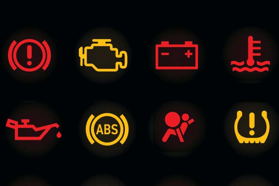
The illumination of a malfunction indicator light (MIL) is a universally recognized symbol of distress in complex technological systems. While most commonly associated with the “Check Engine” light in modern automobiles, the underlying principle extends across a vast array of devices, from industrial machinery to sophisticated computing systems and even smart home appliances. At its core, an MIL serves as a critical communication channel, alerting users or operators to an anomaly, fault, or condition that deviates from expected operational parameters, thereby preventing further damage, ensuring safety, or maintaining optimal performance.
Understanding what triggers an MIL, how to interpret its message, and the diagnostic steps required is crucial in a world increasingly reliant on technology. It’s not just a warning; it’s an invitation to a deeper technical investigation, often preventing minor issues from escalating into costly repairs or critical system failures.
Understanding the Malfunction Indicator Light (MIL) System
The malfunction indicator light is more than just an illuminated icon; it’s the visible tip of a sophisticated diagnostic iceberg. Its primary function is to draw immediate attention to a system fault that requires investigation.
The Universal Warning Signal
In automotive contexts, the MIL is often referred to as the Check Engine Light (CEL), and it’s an integral part of the On-Board Diagnostics (OBD-II) system mandated in vehicles manufactured after 1996 in many parts of the world. This standardization ensures that regardless of make or model, a driver can recognize a fundamental issue. However, the concept is far broader. In server racks, blinking amber lights might indicate a failing hard drive; on a factory floor, a specific warning light could signal an overheating motor or a sensor malfunction. In each instance, the light acts as a primary, immediate alert that something is amiss, demanding attention before a complete breakdown occurs or safety is compromised. It represents a deviation from the system’s normal operational envelope, whether that relates to emissions, performance, safety, or core functionality.
How MILs Work
The operation of an MIL is rooted in continuous monitoring and algorithmic decision-making. Within a system, numerous sensors tirelessly collect data on various parameters—engine speed, oxygen levels, temperature, voltage, data integrity, pressure, and more. This data is fed into a central Electronic Control Unit (ECU) or a similar processing unit, which constantly compares incoming sensor readings against pre-programmed normal operating ranges and thresholds.
If a sensor reading falls outside the acceptable range for a predetermined period, or if conflicting data arises (e.g., a critical component reports “off” while the system expects “on”), the ECU logs a Diagnostic Trouble Code (DTC). This DTC is a specific alphanumeric code that pinpoints the nature and location of the fault. Simultaneously, the ECU commands the MIL to illuminate on the dashboard or control panel.
The manner of illumination often conveys further information:
- Solid Light: Typically indicates a non-critical but persistent issue that needs attention soon, such as a minor emissions leak or a faulty sensor that isn’t immediately impacting drivability or system stability.
- Flashing or Blinking Light: This is a severe warning, signaling a critical fault that could cause immediate damage to the system components (e.g., a severe engine misfire causing catalytic converter damage) or pose a safety risk. A flashing MIL demands immediate action, often advising the user to stop operation as soon as safely possible.
The complexity lies not just in the light itself, but in the intricate network of sensors, control units, and diagnostic algorithms that constantly safeguard the system’s integrity.
Common Triggers for Vehicle MILs
While MILs exist in various tech domains, their prevalence and standardization in automotive systems make them an excellent case study for understanding common triggers. Most vehicle MILs are emission-related, but they can also signal deeper engine or transmission issues.
Emission-Related Issues
A significant portion of MIL illuminations in vehicles stems from issues impacting the vehicle’s emissions system. These are often the easiest to fix, or the most insidious to diagnose.
- Loose or Faulty Gas Cap: Surprisingly common, a loose or damaged fuel filler cap can cause the MIL to light up. The cap is a vital component of the Evaporative Emission Control (EVAP) system, which prevents fuel vapors from escaping into the atmosphere. A leaky cap can trigger a “small EVAP leak” code.
- Faulty Oxygen Sensor (O2 Sensor): O2 sensors measure the amount of unburned oxygen in the exhaust. This data is crucial for the ECU to adjust the fuel-air mixture for optimal combustion and emissions. A failing O2 sensor can lead to increased fuel consumption and higher emissions.
- Catalytic Converter Inefficiency: The catalytic converter reduces harmful pollutants in exhaust gases. If it’s failing due to age, damage, or poisoning (often from persistent misfires or excessive oil consumption), it can trigger an MIL, often indicating a P0420/P0430 code (Catalyst System Efficiency Below Threshold). This is typically a costly repair.
- Mass Airflow Sensor (MAF Sensor) Issues: The MAF sensor measures the amount of air entering the engine. This information is vital for the ECU to calculate the correct amount of fuel to inject. A dirty or faulty MAF sensor can lead to rough idling, poor acceleration, and increased fuel consumption.
- Spark Plugs and Ignition Coils: Misfires, often caused by worn spark plugs, faulty ignition coils, or bad spark plug wires, can lead to unburned fuel entering the exhaust system. This not only causes rough running but can also quickly damage the catalytic converter, often resulting in a flashing MIL.
Engine Performance & Safety
Beyond emissions, MILs can signal more direct engine performance or safety concerns.
- Engine Misfires: As mentioned, misfires are a direct performance issue. They mean one or more cylinders aren’t combusting fuel properly, leading to reduced power, poor fuel economy, and potential engine damage.
- Transmission Issues: While often indicated by a separate transmission warning light, some transmission faults that impact engine load or communication with the ECU can trigger the MIL. These might include sensor failures within the transmission or issues with its electronic control unit.
- Evaporative Emission (EVAP) System Leaks: Apart from the gas cap, other components of the EVAP system, such as hoses, purge valves, or vent valves, can develop leaks. These leaks allow fuel vapors to escape, triggering an MIL for an EVAP system fault.
Sensor Malfunctions
It’s crucial to understand that an MIL often indicates a sensor’s perception of a problem, not always a catastrophic failure of the underlying component itself. A sensor sending incorrect data can lead the ECU to believe there’s a fault. For example, a faulty engine coolant temperature sensor might tell the ECU the engine is cold when it’s hot, leading to an incorrect fuel mixture and an MIL, even if the engine itself is running fine otherwise. Diagnosing these requires verifying sensor readings against actual conditions.
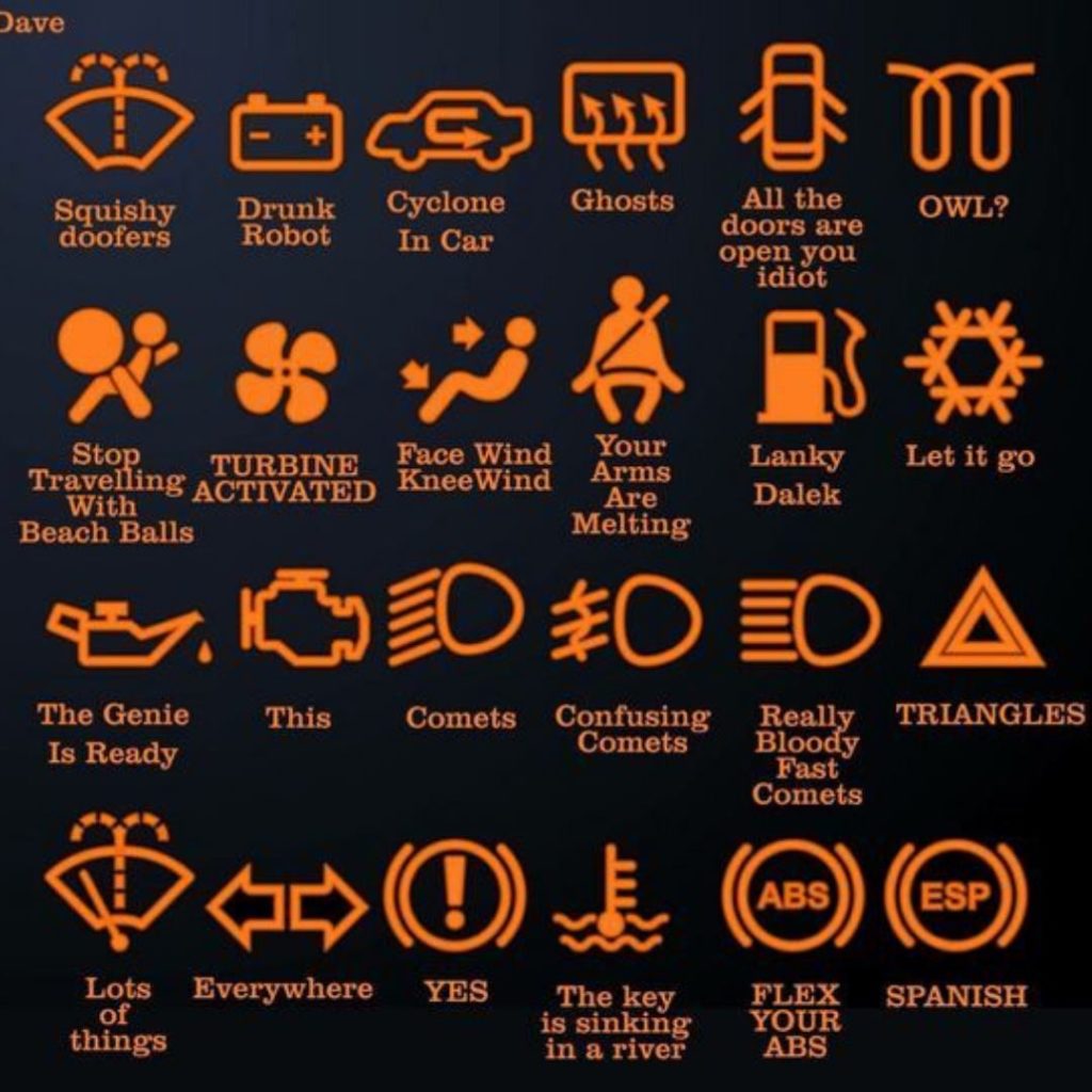
Decoding the Light: Diagnostic Tools and Procedures
When an MIL illuminates, the first step is always to retrieve the Diagnostic Trouble Code (DTC). This is where specialized tools come into play, forming the backbone of any effective diagnostic process.
OBD-II Scanners
An OBD-II scanner is an indispensable tool for anyone facing an MIL. These devices connect to the OBD-II port (typically located under the dashboard) and communicate with the vehicle’s ECU to retrieve stored DTCs.
- Basic Code Readers: These inexpensive devices simply display the DTC (e.g., P0301 for Cylinder 1 Misfire) and often offer a brief generic description. They are useful for quickly identifying the general area of a problem.
- Advanced Diagnostic Tools: Professional-grade scanners and software offer much more. They can display “freeze frame data” (a snapshot of sensor readings at the exact moment the fault occurred), live sensor data streams, run component tests, reset adaptive values, and even reprogram ECUs. This depth of information is critical for pinpointing intermittent issues or validating repairs.
Interpreting Diagnostic Trouble Codes (DTCs)
DTCs are standardized alphanumeric codes, primarily in the format Pxxxx for powertrain issues (which are the most common MIL triggers).
- P0xxx: Generic codes, shared across all manufacturers.
- P1xxx: Manufacturer-specific codes, providing more detailed information for a particular vehicle make.
The initial letter indicates the system: P for Powertrain, B for Body, C for Chassis, U for Network Communication.
It’s vital to understand that a DTC is a starting point, not a definitive solution. For example, a P0420 (Catalyst System Efficiency Below Threshold) doesn’t automatically mean the catalytic converter is bad. It could be caused by an upstream oxygen sensor fault, an exhaust leak, or an engine misfire that’s damaging the converter. Relying solely on the code without further investigation can lead to misdiagnosis and unnecessary parts replacement.
The Diagnostic Process
A professional diagnostic process goes far beyond merely reading a code.
- Verify the Complaint: Understand the symptoms the user is experiencing (e.g., rough idle, lack of power, smoke).
- Retrieve DTCs and Freeze Frame Data: This provides the specific codes and conditions when the fault occurred.
- Research the Code: Consult service manuals, technical service bulletins (TSBs), and online databases for known causes and diagnostic flowcharts related to that specific DTC for the vehicle’s make and model.
- Visual Inspection: Look for obvious issues like loose wires, cracked hoses, fluid leaks, or physical damage.
- Component Testing: Use multimeters, oscilloscopes, smoke machines (for EVAP leaks), or dedicated diagnostic software to test individual sensors and actuators to confirm their operation.
- Verify the Repair: After a repair, clear the codes and perform a test drive, ensuring the system monitors run and pass without the MIL re-illuminating. Sometimes, multiple drive cycles under specific conditions are required for all system monitors to complete.
Proactive Monitoring and Preventative Measures
Preventing an MIL from lighting up in the first place is always preferable to diagnosing and repairing a fault. Modern technology increasingly supports proactive health monitoring, moving beyond reactive warnings.
Regular Maintenance
Adhering to a robust maintenance schedule is the single most effective way to prevent many MIL triggers.
- Fluid Changes: Regular oil changes, transmission fluid services, and coolant flushes ensure components are properly lubricated and cooled, preventing premature wear that could lead to sensor faults or mechanical failures.
- Filter Replacements: Clean air filters and fuel filters ensure optimal combustion and prevent contaminants from reaching sensitive components.
- Spark Plug and Ignition System Checks: Replacing spark plugs at recommended intervals prevents misfires, which are a common MIL trigger and can damage other expensive components like catalytic converters.
- Battery and Charging System Health: A weak battery or alternator can cause erratic voltage signals, leading to false MIL triggers or issues with sensitive electronic components.
Sensor Health
Sensors are the eyes and ears of the ECU. Keeping them healthy is paramount. During routine service, technicians might inspect oxygen sensors for contamination, clean MAF sensors (with appropriate MAF cleaner), and check wiring harnesses for corrosion or damage. Paying attention to engine cleanliness, avoiding excessive oil leaks, and using quality fuel can also extend sensor life by preventing premature fouling.
Telematics and Predictive Diagnostics
The frontier of MIL prevention lies in telematics and predictive diagnostics. Many modern vehicles and industrial machines are equipped with embedded cellular or Wi-Fi connectivity, constantly streaming operational data to manufacturers or fleet managers.
- Remote Monitoring: This allows for real-time monitoring of hundreds of data points. Anomalies can be flagged before they cross the threshold for an MIL illumination.
- Predictive Maintenance: Algorithms analyze historical data and current trends to predict component failures. For example, subtle changes in vibration patterns or temperature readings might indicate an impending bearing failure in an industrial motor long before a catastrophic event triggers a hard fault MIL.
- Smartphone Integration: OBD-II dongles that pair with smartphone apps can provide consumers with real-time access to their vehicle’s health data, showing pending codes or minor deviations before the MIL even illuminates, empowering them to address issues proactively. This democratizes diagnostics to some extent, bringing basic monitoring capabilities directly to the user.
MILs Beyond Automotive: A Broader Tech Perspective
While vehicles offer the most common example, the concept of a malfunction indicator light is fundamental to troubleshooting and maintaining functionality across diverse technological landscapes.
Computing Systems
In the realm of computing, MILs manifest in various forms.
- Motherboard Error LEDs/Display Codes: High-end motherboards often feature small LED segments or a series of four LEDs (Q-LEDs) that light up in sequence during boot-up. If the system fails to POST (Power-On Self-Test), these lights or codes will indicate the component causing the failure (CPU, RAM, GPU, Boot device). This is a direct parallel to an automotive MIL, pointing to a specific internal hardware fault.
- Hard Drive Health Indicators: Server hard drives and Network Attached Storage (NAS) devices often have status LEDs that change color (e.g., green for healthy, amber for warning, red for failure) to indicate drive health or impending failure, often based on SMART (Self-Monitoring, Analysis, and Reporting Technology) data.
- Network Device Status Lights: Routers, switches, and modems utilize blinking or solid lights to indicate connection status, data transfer, and hardware health. A red or amber light on a modem typically signals a connectivity issue or a hardware malfunction. While not always called an “MIL,” their function is identical: to alert the user to a non-optimal state.
Industrial Machinery & Smart Devices
The principle extends to virtually any complex system requiring reliability and uptime.
- Factory Automation: Programmable Logic Controllers (PLCs) and Human-Machine Interfaces (HMIs) in manufacturing plants use indicator lights and digital error messages to alert operators to sensor failures, motor overloads, emergency stops, or component wear. These systems are often interconnected, providing comprehensive diagnostic feedback to control rooms.
- Aerospace and Maritime Systems: Aircraft cockpits and ship bridges are replete with indicator lights for critical system statuses—engine health, hydraulic pressure, navigation system faults, and more. A single red light can signify a critical system failure demanding immediate pilot or captain intervention.
- Smart Home Devices: Even in consumer smart home technology, the MIL concept exists. A smart thermostat might display an error code if a sensor is faulty or if it loses connection to the network. A smart appliance might have a blinking light pattern indicating an internal fault, guiding a user to a specific troubleshooting step in the manual.

The Future of Malfunction Indicators
The future promises even more sophisticated MIL systems. We are already seeing:
- AI-Powered Diagnostics: Artificial intelligence and machine learning algorithms can process vast amounts of sensor data to detect subtle anomalies that precede traditional MIL triggers, offering predictive maintenance insights with higher accuracy.
- Augmented Reality (AR) for Troubleshooting: Technicians (or even end-users with guided apps) could use AR overlays to visualize component status, access repair instructions, and identify failing parts directly within their field of view.
- Seamless Communication with Service Networks: MILs will increasingly integrate with cloud-based platforms, automatically notifying service centers of an issue, potentially even pre-ordering parts or scheduling an appointment before the user is fully aware of the fault.
In essence, the malfunction indicator light, whether a simple dashboard icon or a complex digital readout, remains a foundational element of system reliability and user interaction with technology, continuously evolving to provide more intelligent, proactive, and interconnected diagnostic insights.
aViewFromTheCave is a participant in the Amazon Services LLC Associates Program, an affiliate advertising program designed to provide a means for sites to earn advertising fees by advertising and linking to Amazon.com. Amazon, the Amazon logo, AmazonSupply, and the AmazonSupply logo are trademarks of Amazon.com, Inc. or its affiliates. As an Amazon Associate we earn affiliate commissions from qualifying purchases.