In the intricate world of digital electronics, where every operation hinges on the precise manipulation of binary data, the flip-flop stands as an unsung hero. Far from being a casual piece of footwear or a change of mind, a flip-flop in technology is a fundamental sequential logic circuit, serving as the most basic unit of digital memory. It’s the invisible workhorse that enables computers to remember states, process instructions sequentially, and form the backbone of nearly every digital device we interact with daily, from smartphones to supercomputers. Understanding the flip-flop is essential to grasping how digital systems store information and execute tasks over time.
The Fundamental Building Block of Digital Memory
At its core, a flip-flop is a bistable multivibrator, meaning it has two stable states and can remain in either of them indefinitely until an external trigger causes it to switch. These two states are typically represented as ‘0’ (low voltage) and ‘1’ (high voltage), corresponding to the binary digits that form the language of digital electronics. This ability to maintain a state makes the flip-flop the smallest storage element in sequential logic, capable of holding a single bit of information.
Latch vs. Flip-Flop: Understanding the Nuance
While often used interchangeably, there’s a subtle but crucial distinction between a latch and a flip-flop in digital circuit design. Both are bistable devices, but their method of changing state differs. Latches are level-triggered, meaning their output can change as long as the enabling input (e.g., a clock pulse being high) is active. This makes them susceptible to glitches and can lead to unpredictable behavior in complex synchronous systems.
Flip-flops, conversely, are edge-triggered. They only change their output state on the rising edge (transition from low to high) or the falling edge (transition from high to low) of a clock signal. This edge-triggering makes flip-flops much more reliable for synchronous digital systems, where all changes need to be precisely synchronized to a master clock. The edge-triggered nature ensures that outputs only update at very specific, predictable moments, preventing race conditions and ensuring data integrity. For the purpose of general understanding, however, “flip-flop” is often used broadly to refer to both latches and edge-triggered devices, with the context usually clarifying the specific type.
Bistable Multivibrator: The Core Concept
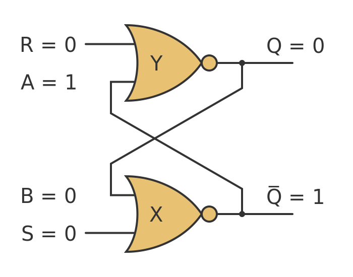
The “bistable” nature of a flip-flop is achieved through positive feedback. Typically, this involves two cross-coupled inverters or NOR/NAND gates. Imagine two inverters, where the output of the first feeds into the input of the second, and the output of the second feeds back into the input of the first. If one output is high, the other must be low, and vice-versa, creating a stable loop that can hold either of these two states. External control inputs are then added to allow the device to be forced into a specific state, effectively “writing” a 0 or 1. This simple, elegant design is what allows a single bit of information to be retained without continuous input, forming the memory backbone of all digital systems.
How Flip-Flops Store Information: States and Triggers
The true utility of a flip-flop lies in its ability to not only store a bit but also to change that stored bit based on specific inputs and timing signals. This dynamic capability is what allows for the execution of complex algorithms and the sequential flow of data in processors.
The ‘Set’ and ‘Reset’ Actions
The most basic flip-flops, like the SR (Set-Reset) type, have inputs dedicated to controlling their state. A ‘Set’ input, when activated, forces the flip-flop into the ‘1’ state. Conversely, a ‘Reset’ input forces it into the ‘0’ state. When neither is active, the flip-flop holds its previous state. This direct control forms the fundamental mechanism for writing data into memory. However, simple SR flip-flops can suffer from an indeterminate state if both Set and Reset are active simultaneously, which is why more sophisticated types were developed.
Clock Signals and Edge-Triggering
The introduction of a clock signal revolutionized the reliability of sequential circuits. A clock is a periodic signal that oscillates between high and low voltage at a fixed frequency, acting as the heartbeat of a digital system. In edge-triggered flip-flops, data is only sampled and loaded on a specific transition (edge) of this clock signal. For example, a positive edge-triggered flip-flop will only capture its input and update its output when the clock signal transitions from low to high.
This precise synchronization prevents “race conditions,” where the timing of different signals arriving at different parts of a circuit could lead to unpredictable results. By ensuring all memory elements update simultaneously at a specific clock edge, the system maintains a consistent state and operates predictably. The clock signal is thus crucial for orchestrating the vast number of operations occurring within a microprocessor every second.
Common Types of Flip-Flops and Their Applications
While the underlying principle remains the same, several types of flip-flops have been developed, each with slightly different input/output behaviors and suited for specific applications.
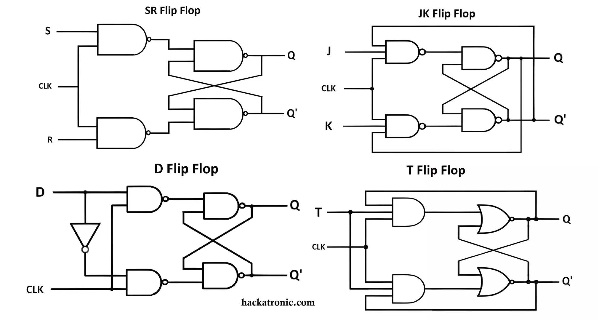
SR Flip-Flop (Set-Reset)
The SR flip-flop is the simplest form, often implemented using cross-coupled NOR or NAND gates. It has two inputs, Set (S) and Reset (R), and two outputs, Q and Q-not (the complement of Q).
- S=1, R=0: Sets Q to 1 (Q=1, Q-not=0)
- S=0, R=1: Resets Q to 0 (Q=0, Q-not=1)
- S=0, R=0: Retains previous state
- S=1, R=1: This is the “forbidden” state, leading to an unpredictable output as both Q and Q-not try to be 0, creating ambiguity.
Due to this forbidden state and its level-triggered nature (when implemented as a latch), SR flip-flops are typically used in simpler control applications where this condition can be avoided or in asynchronous circuits.

D Flip-Flop (Data or Delay)
The D flip-flop is arguably the most widely used type. It has a single data input (D) and a clock input (CLK). On the active edge of the clock, the value present at the D input is transferred to the Q output.
- CLK active edge: Q becomes equal to D.
This type is essential for creating shift registers, data latches, and memory cells, as it acts as a perfect one-bit delay element, holding the data until the next clock pulse. Its simplicity and robust behavior make it ideal for synchronous data storage.
JK Flip-Flop (Jaguar-Kilby or Jack Kilby)
The JK flip-flop is a more versatile version of the SR flip-flop, eliminating the forbidden state. It has two inputs, J (for Set) and K (for Reset), and a clock input.
- J=1, K=0: Sets Q to 1
- J=0, K=1: Resets Q to 0
- J=0, K=0: Retains previous state
- J=1, K=1: Toggles the state of Q (if Q was 0, it becomes 1; if Q was 1, it becomes 0).
The “toggle” feature makes the JK flip-flop particularly useful in counters and frequency dividers, where changing state with each clock pulse is required.
T Flip-Flop (Toggle)
The T flip-flop is a simplified version of the JK flip-flop, where both J and K inputs are tied together to a single ‘T’ input.
- T=0: Retains previous state
- T=1: Toggles the state of Q on the active clock edge.
T flip-flops are specialized for applications requiring repeated toggling, such as frequency dividers (dividing the clock frequency by two) and binary counters.
The Role of Flip-Flops in Modern Technology
While seemingly simple, the ability of flip-flops to store a single bit and change its state synchronously forms the bedrock of complex digital systems. They are not merely standalone components but integrated into vast arrays to perform sophisticated functions.
Registers and Counters
- Registers: A register is a collection of D flip-flops (or sometimes other types) arranged in parallel to store multiple bits of data (a “word”). For example, an 8-bit register uses eight D flip-flops to store an 8-bit byte. Registers are crucial within CPUs for temporarily holding data, instructions, and memory addresses that the processor is currently working on.
- Counters: Counters are sequential circuits built from flip-flops that cycle through a predefined sequence of states. Each state represents a binary number, and the counter increments or decrements with each clock pulse. They are used for timing, frequency division, event counting, and controlling the sequence of operations in digital systems.
Memory Units (RAM)
Dynamic Random Access Memory (DRAM), the most common type of main memory in computers, uses capacitors to store bits. However, Static Random Access Memory (SRAM), known for its speed and stability, is built directly from flip-flops (typically six transistors per bit). While more expensive and consuming more power than DRAM, SRAM’s non-refreshing nature and faster access times make it ideal for CPU caches and other applications requiring high-speed data retrieval.
State Machines and Control Logic
Finite State Machines (FSMs) are conceptual models used to design control logic in digital systems. An FSM transitions between a finite number of states based on inputs and a clock signal. The current state of an FSM is typically stored in a set of flip-flops. These state machines are fundamental to controlling the sequence of operations in everything from traffic light controllers to complex microprocessor pipelines, dictating what action happens next based on the system’s current condition.
Beyond the Basics: Advanced Concepts and Future Trends
The fundamental concept of the flip-flop has remained constant, but its implementation and optimization continue to evolve, particularly in the context of increasing computational demands and power efficiency.
Clock Gating and Power Optimization
In modern integrated circuits, a significant portion of power consumption comes from the clock tree, which distributes the clock signal to all flip-flops. Clock gating is a technique used to reduce this power consumption by dynamically disabling the clock signal to parts of the circuit that are not currently active. This is often achieved by adding AND or OR gates to the clock lines, controlled by enable signals. While effective for power saving, careful design is needed to avoid introducing clock skew or glitches.
Challenges in High-Speed Design
As clock frequencies climb into the gigahertz range, the timing behavior of flip-flops becomes critically important. Issues like setup time (data must be stable before the clock edge) and hold time (data must remain stable after the clock edge) become extremely tight, requiring sophisticated design techniques and precise manufacturing to ensure reliable operation. Variations in manufacturing processes, temperature, and voltage can all impact these timing parameters, posing significant challenges for designers pushing the limits of speed and performance in processors and other high-speed digital systems. The relentless pursuit of faster and more efficient computing continues to drive innovation in flip-flop design and their integration into complex architectures.
aViewFromTheCave is a participant in the Amazon Services LLC Associates Program, an affiliate advertising program designed to provide a means for sites to earn advertising fees by advertising and linking to Amazon.com. Amazon, the Amazon logo, AmazonSupply, and the AmazonSupply logo are trademarks of Amazon.com, Inc. or its affiliates. As an Amazon Associate we earn affiliate commissions from qualifying purchases.