
The journey from a digital concept to a physical object is the core magic of 3D printing. However, your 3D printer does not possess the inherent ability to “read” a 3D model file like a human reads a book. To bridge the gap between a design and a functional part, you require a critical piece of software known as a slicer. A slicer is the bridge between the virtual world of Computer-Aided Design (CAD) and the physical world of additive manufacturing. Without it, your 3D printer would be nothing more than a collection of motors, heating elements, and sensors with no instructions on how to move.
The Fundamental Role of the Slicer
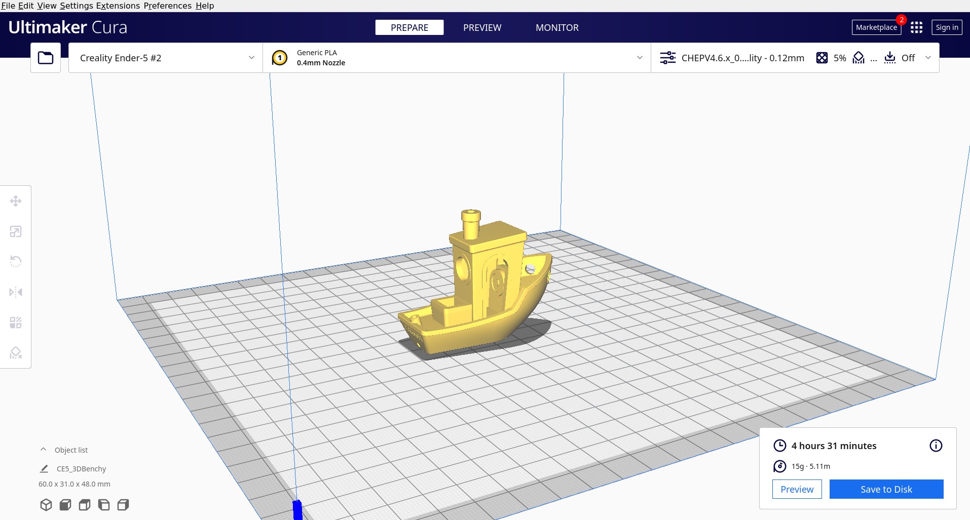
At its most basic level, a slicer takes a 3D model—typically in an STL, OBJ, or 3MF file format—and translates it into a language the printer understands: G-code. G-code is a numerical control programming language that tells the printer precisely where to move its nozzle, how fast to extrude material, and at what temperature to heat the filament.
Deconstructing the Geometry
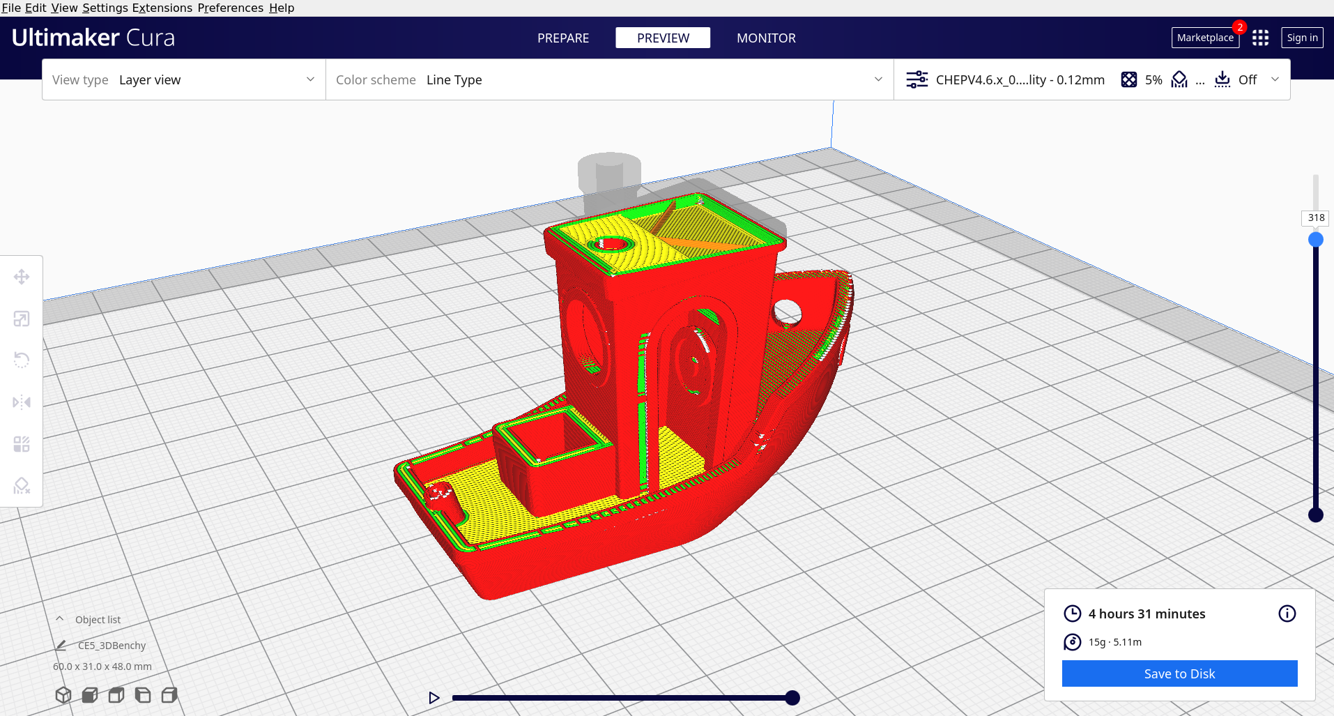
When you import a 3D model into slicer software, the program analyzes the geometry of the object. Since 3D printers work additively—meaning they build objects layer by layer from the bottom up—the slicer must “slice” the solid 3D digital model into hundreds or thousands of thin, horizontal two-dimensional layers. Each of these slices corresponds to a single pass of the printer head.
The Pathing Logic
Once the layers are calculated, the slicer determines the toolpath. This involves calculating the coordinates for the printer’s X, Y, and Z axes. The software determines the most efficient route for the print head to follow, ensuring that the plastic is deposited in a way that provides structural integrity while minimizing print time. It decides how to fill the interior of the part, how to support overhanging geometry, and how to create the external walls or “shells” that define the object’s surface finish.
Core Parameters That Define Print Quality
While the slicer handles the heavy lifting of geometry calculation, the user holds the reins regarding settings. Understanding these variables is the difference between a successful print and a “spaghetti monster” of failed filament.
Layer Height and Resolution
Layer height is perhaps the most significant setting in the slicer. It dictates the thickness of each individual layer printed. A lower layer height—such as 0.1mm—results in finer detail and smoother surfaces, but significantly increases print time because the printer must perform more passes. A higher layer height, like 0.3mm, allows for faster production but sacrifices surface quality, often resulting in visible “stair-stepping” or ridges on the side of the model.
Infill Density and Patterns
You rarely need an object to be 100% solid. Doing so wastes material and increases printing time unnecessarily. Slicers allow you to define an “infill” percentage and pattern. Infill is the internal structure of the part. If you are printing a display piece, 5-10% infill may be sufficient. If you are creating a functional mechanical part, you might opt for 40-50% or even higher. Common patterns include grid, cubic, gyroid, and honeycomb, each offering different trade-offs between material usage, printing speed, and structural strength.
Perimeters and Shells
Perimeters, or walls, refer to the outer layers of your print. Increasing the number of perimeters makes the object significantly stronger, as the outer shell usually bears the brunt of physical stress. A typical slicer setup might use two or three perimeters, but for high-stress applications, adding extra walls is often more effective than simply increasing the infill density.

Handling Complexity: Supports and Bed Adhesion
Not every 3D model is easy to print. Gravity is a constant adversary in additive manufacturing. When a design features overhangs—sections of the print that extend out into thin air—the printer needs a way to support that material until it hardens.
Automatic and Manual Support Structures
The slicer identifies these overhangs automatically. When the angle of a feature exceeds a certain threshold (usually 45 degrees), the slicer generates support structures. These are temporary, sacrificial pillars or scaffolds that the printer builds beneath the overhang. After the print is complete, these supports are snapped or peeled away. Sophisticated slicers allow users to customize where supports are placed to avoid damaging the surface finish of the finished part.
Rafts, Brims, and Skirts
Getting the first layer of a print to stick to the build plate is crucial. If the first layer fails, the entire print is ruined. Slicers offer several tools to assist with bed adhesion:
- Skirt: A single-line outline printed around the object before the print begins. It serves to prime the nozzle and ensure the filament is flowing smoothly.
- Brim: A series of lines attached to the bottom edge of the model that extends outward. It increases the surface area of the base, helping to prevent the edges of the part from curling or lifting (known as warping).
- Raft: A thick, horizontal mesh platform printed first, on top of which the actual model is built. This is used when the model has a small contact area with the print bed or is prone to adhesion issues.
Advanced Slicer Features for Prototyping
Modern slicers have evolved far beyond basic geometry processing. They now include features that allow for professional-grade fabrication, often rivaling the capabilities of industrial-grade 3D printers.
Modifier Meshes and Variable Settings
One of the most powerful features in contemporary software like PrusaSlicer or Cura is the ability to use “modifiers.” A modifier allows you to apply different settings to specific parts of a single model. For example, if you are printing a mechanical gear, you might want the central hole to have more walls for strength, while the outer teeth need a specific infill pattern for flexibility. Modifiers enable you to adjust these parameters within defined zones of the object without changing the settings for the entire print.
Sequential Printing
Usually, printers handle objects one layer at a time across all parts on the bed. However, if you are printing multiple small items, you can enable sequential printing. The slicer will arrange the objects so that the printer completes one individual object entirely before moving on to the next. This reduces the amount of “travel” movement the nozzle has to make, potentially reducing stringing—the annoying wisps of plastic that can appear between disconnected sections of a print.
Material Management and Flow Control
Different materials—PLA, PETG, ABS, TPU—behave differently. A slicer stores these differences in “profiles.” These profiles automatically adjust temperatures for the nozzle and the heated bed, as well as cooling fan speeds. More importantly, they manage the “flow rate” or “extrusion multiplier.” Because different plastics expand and contract at different rates, the slicer must be told exactly how much plastic to push out to ensure dimensions remain accurate to the original design.
The Evolution of Slicer Software
As 3D printing moves from hobbyist garages into professional engineering firms and small manufacturing centers, the role of the slicer is becoming increasingly critical. We are seeing a move toward cloud-based slicing, where computation happens on remote servers to handle incredibly complex models without taxing the user’s local hardware. Additionally, artificial intelligence is beginning to play a role in slicers, with algorithms capable of suggesting optimal orientations for strength or identifying potential print failures before the first layer is even laid down.
In conclusion, the slicer is the translator of the 3D printing world. It is the gatekeeper of quality and the primary interface through which you control the physics of the printing process. By mastering your slicer—understanding the interplay between layer height, infill, supports, and material profiles—you transform from a passive user into a skilled fabricator, capable of turning digital data into physical reality with precision and efficiency. Whether you are creating a simple trinket or a complex mechanical housing, the slicer remains the most important tool in your additive manufacturing toolkit.
aViewFromTheCave is a participant in the Amazon Services LLC Associates Program, an affiliate advertising program designed to provide a means for sites to earn advertising fees by advertising and linking to Amazon.com. Amazon, the Amazon logo, AmazonSupply, and the AmazonSupply logo are trademarks of Amazon.com, Inc. or its affiliates. As an Amazon Associate we earn affiliate commissions from qualifying purchases.