The world is increasingly reliant on high-speed data, and at the heart of this revolution lies fiber optic cable. Unlike traditional copper wiring, fiber optics transmit data as pulses of light through incredibly thin strands of glass or plastic. This technology offers unparalleled bandwidth, speed, and reliability, making it the backbone of modern telecommunications, internet services, and even advanced industrial applications. While the thought of installing fiber optic cable might seem daunting, especially for those accustomed to simpler wiring projects, understanding the process, the necessary tools, and the critical steps involved can demystify the undertaking. This guide will walk you through the essential aspects of how to install fiber optic cable, whether for a home network upgrade, a business infrastructure project, or even a more extensive deployment.
Understanding the Fundamentals of Fiber Optic Installation
Before diving into the practicalities of installation, it’s crucial to grasp the fundamental principles and components that govern fiber optic networks. This foundational knowledge will not only make the installation process smoother but also equip you to troubleshoot potential issues and ensure the long-term performance of your fiber optic system.
The Anatomy of Fiber Optic Cable
Fiber optic cables are more complex than their copper counterparts, and understanding their structure is key to handling them correctly. A typical fiber optic cable consists of several layers, each serving a vital purpose:
- Core: This is the central part of the fiber where light signals travel. It’s made of extremely pure glass (silica) or plastic. The refractive index of the core is higher than that of the cladding, which is essential for confining the light within the core through total internal reflection.
- Cladding: Surrounding the core, the cladding is another layer of glass or plastic with a slightly lower refractive index than the core. This difference in refractive indices is what guides the light signals along the core, preventing them from escaping.
- Coating (Buffer): This protective layer, often made of plastic, shields the delicate core and cladding from physical damage, moisture, and abrasion. It’s the primary buffer that provides mechanical strength to the fiber.
- Strength Members: These are typically made of aramid yarn (like Kevlar) or fiberglass rods and are embedded in the cable’s jacket to provide tensile strength. They protect the fragile glass fibers from stretching and breaking during installation and in future use.
- Jacket (Outer Sheath): This is the outermost layer of the cable, providing overall protection against environmental factors such as crushing, abrasion, chemicals, and sunlight. The type of jacket material (e.g., PVC, LSZH – Low Smoke Zero Halogen) is chosen based on the installation environment.
Types of Fiber Optic Cable
Fiber optic cables come in two primary types, distinguished by how light travels through them:
- Single-Mode Fiber (SMF): This type of fiber has a very small core diameter (typically 9 micrometers) that allows only one mode of light to propagate at a time. This single path minimizes signal dispersion, allowing light signals to travel over extremely long distances with minimal signal loss. SMF is ideal for long-haul telecommunications, high-speed internet backbones, and applications requiring maximum bandwidth over extended ranges.
- Multi-Mode Fiber (MMF): MMF has a larger core diameter (typically 50 or 62.5 micrometers) that allows multiple modes of light to travel simultaneously. While easier to connect and terminate, the different paths light takes can lead to modal dispersion, limiting the effective transmission distance compared to SMF. MMF is commonly used in shorter-distance applications such as Local Area Networks (LANs), data centers, and premise wiring.
Essential Tools and Equipment for Installation
Successfully installing fiber optic cable requires specialized tools designed for precise handling and termination of these delicate materials. Using the wrong tools can lead to damaged fibers, poor signal quality, and ultimately, a failed installation.
- Fiber Optic Strippers: These are crucial for removing the protective buffer coatings without damaging the glass fiber. They come in various types, including those for primary coating and secondary buffer coatings. Precision is paramount here.
- Fiber Optic Cleaver: A high-precision cleaving tool is essential for creating a perfectly flat, perpendicular end face on the fiber. This clean break is critical for achieving low insertion loss when connecting fibers via splicing or connectors.
- Fusion Splicer: For permanent and low-loss fiber optic connections, a fusion splicer is the industry standard. It precisely aligns the ends of two fibers and uses an electric arc to fuse them together. This method yields the most robust and reliable connections for long-term performance.
- Fiber Optic Connectors: If fusion splicing isn’t feasible or desirable, mechanical connectors can be used. These connectors have a pre-polished fiber end and an alignment mechanism to connect two fiber ends. While generally easier to install in the field, they can sometimes have slightly higher insertion loss than fusion splices. Common connector types include SC, LC, ST, and MTRJ.
- Fiber Optic Inspection Scope: Before and after splicing or connecting, inspecting the fiber end faces for cleanliness and damage is vital. An inspection scope allows you to magnify the fiber end and identify any contaminants or imperfections that could degrade signal quality.
- Optical Power Meter (OPM) and Light Source: To test the performance of the installed fiber, an OPM and a compatible light source are indispensable. The light source injects a calibrated light signal into the fiber, and the OPM measures the power of that signal at the other end, allowing for the calculation of insertion loss.
- Cable Pulling Tools: For longer runs, specialized tools like cable grips, pulling eyes, and even powered winches might be necessary to safely and effectively pull the fiber optic cable through conduits or along pathways.
- Safety Gear: This includes safety glasses (to protect from flying glass fragments), gloves, and potentially ear protection when using noisy equipment like fusion splicers.
Planning Your Fiber Optic Installation
A well-executed fiber optic installation begins with meticulous planning. Rushing into the physical work without a clear strategy can lead to costly mistakes, delays, and a compromised network. This phase involves understanding your specific needs, surveying the installation environment, and designing the optimal path for your fiber optic cables.
Assessing Your Needs and Objectives
Before any tools are picked up, clearly define the purpose of your fiber optic installation.
- Bandwidth Requirements: What kind of speeds do you need? Are you supporting heavy data transfer, high-definition video streaming, or large-scale cloud computing? Different applications have varying bandwidth demands that will influence the type of fiber and the number of strands required.
- Distance and Reach: How far will the data need to travel? This is a critical factor in deciding between single-mode and multi-mode fiber. Long-distance deployments will almost certainly necessitate SMF, while shorter runs within a building might be adequately served by MMF.
- Future Scalability: Consider your future needs. Will your bandwidth requirements increase over time? Installing more fiber strands than immediately necessary can be a cost-effective way to accommodate future growth without extensive re-wiring.
- Environmental Considerations: Where will the cable be installed? Will it be indoors, outdoors, buried, or run through aerial pathways? Each environment presents unique challenges and requires specific cable types and protection measures. For instance, outdoor cables need to be UV-resistant and potentially waterproof.
Site Survey and Pathway Design
A thorough site survey is paramount for identifying the best routes for your fiber optic cables. This involves mapping out the entire pathway from the source to the destination, noting any potential obstacles or challenges.
- Mapping Existing Infrastructure: Identify the locations of network termination points, existing conduits, junction boxes, and any other relevant infrastructure.
- Obstacle Identification: Note any physical barriers such as walls, ceilings, floors, furniture, machinery, or existing electrical wiring that the cable must navigate.
- Path Selection: Determine the most efficient and least disruptive pathways for cable runs. This might involve using existing conduit, drilling new holes, or utilizing overhead cable trays. Always aim for routes that minimize sharp bends, which can cause signal degradation.
- Bend Radius Considerations: Fiber optic cables have a minimum bend radius – the tightest curve they can tolerate without damage or signal loss. This radius is specified by the manufacturer and must be adhered to during planning and installation. Exceeding the bend radius is a common cause of fiber optic failure.
- Protection and Segregation: Plan for how the fiber optic cables will be protected from physical damage. This includes using appropriate conduits, raceways, or cable trays. It’s also good practice to segregate fiber optic cables from power cables to prevent electromagnetic interference, although this is less of a concern for fiber optics than copper.
- Environmental Controls: For critical deployments, consider environmental factors like temperature fluctuations, humidity, and potential for rodent or insect damage, especially for outdoor or in-wall installations.
Cable Management and Termination Points
Proper cable management and thoughtful planning of termination points are crucial for a clean, organized, and maintainable fiber optic network.
- Labeling: Implement a robust labeling system from the outset. Each cable end, patch panel port, and termination point should be clearly labeled to facilitate identification and troubleshooting.
- Patch Panels and Distribution Frames: These are used at network closets or data centers to organize and terminate fiber optic cables. They allow for easy connection and disconnection of fiber runs via patch cords.
- Splice Closures: For outdoor or underground installations, splice closures are used to protect and manage fiber optic splices. They are designed to be waterproof and environmentally resistant.
- Cable Slack: Always leave sufficient slack at termination points and junction boxes. This slack provides flexibility for future moves, adds, or changes, and prevents strain on the connections. A common practice is to leave at least 3-5 feet of slack.
The Practical Installation Process
With careful planning and the right tools, the actual installation of fiber optic cable can proceed. This section outlines the key steps involved, from preparing the cable to making the final connections.

Cable Preparation and Handling
The delicate nature of fiber optic cables necessitates a careful approach during preparation.
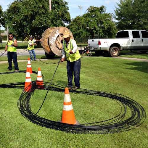
- Unspooling the Cable: Gently unspool the fiber optic cable from its reel. Avoid pulling too hard or allowing the cable to twist, as this can damage the fibers within.
- Stripping the Buffer Coatings: Using specialized fiber optic strippers, carefully remove the protective buffer coatings from the fiber ends. It’s crucial to use the correct stripper for the specific coating type and to avoid nicking or scratching the glass fiber. This often involves multiple stripping steps to remove different layers of coating.
- Cleaning the Fiber: After stripping, it’s essential to clean the exposed glass fiber with an approved fiber optic cleaning solution and lint-free wipes. Contamination at this stage can severely impact signal transmission.
Fiber Optic Splicing vs. Connectorization
The method you choose for connecting fiber optic cables depends on the application, desired performance, and available tools.
Fusion Splicing
Fusion splicing is the preferred method for permanent, high-performance connections.
- Cleaving the Fiber: After stripping and cleaning, use a precision cleaver to create a perfectly flat, angled end face on the fiber. This is a critical step; any imperfections will result in high insertion loss.
- Aligning the Fibers: The fusion splicer uses precision alignment mechanisms to bring the cleaved fiber ends into exact contact.
- Arc Fusion: The splicer then generates an electric arc that melts and fuses the two fiber ends together. Advanced splicers can automatically analyze the splice quality and make adjustments.
- Protection: The resulting splice is then covered with a heat-shrinkable splice protector to provide mechanical strength and environmental protection.
Connectorization (Mechanical Connectors)
Mechanical connectors offer a quicker, tool-less (in some cases) method for terminating fiber optic cables, especially in field applications.
- Preparing the Fiber: The fiber end is stripped, cleaned, and cleaved as for fusion splicing.
- Inserting into the Connector: The fiber is carefully inserted into the mechanical connector body, often until a visible indicator shows it’s properly seated.
- Activating the Connector: Some mechanical connectors have a lever or mechanism that is actuated to secure the fiber and create the connection.
The choice between splicing and connectorization often comes down to a trade-off between performance (fusion splicing generally offers lower loss and better reliability) and ease of installation/field deployment (mechanical connectors are quicker).
Testing and Verification
Once the cables are run and terminated, rigorous testing is essential to ensure the integrity and performance of the fiber optic link.
- Visual Inspection: Use an inspection scope to examine the end faces of all connectors and splices for cleanliness and any signs of damage.
- Insertion Loss Testing: Connect a calibrated optical light source to one end of the fiber run and an optical power meter to the other. Measure the power of the light signal transmitted. Comparing this to the known output power of the light source allows you to calculate the total insertion loss for the link. This loss should be within acceptable industry standards for the type of fiber and the length of the run.
- Optical Time Domain Reflectometry (OTDR): For longer or more complex networks, an OTDR is an invaluable tool. It sends pulses of light down the fiber and analyzes the reflected signals to map the fiber path, identify splices, connectors, bends, and pinpoint any faults or breaks along the cable.
Best Practices and Troubleshooting
Adhering to best practices throughout the installation process will significantly reduce the likelihood of issues. However, when problems arise, knowing how to troubleshoot effectively is crucial for restoring network functionality.
Maintaining Cleanliness
This cannot be stressed enough: cleanliness is paramount in fiber optic installations.
- Work Environment: Keep your workspace as clean as possible. Avoid dusty or dirty areas.
- Handling: Never touch the polished end face of a connector or a cleaved fiber with your bare fingers. Skin oils and dirt are major contaminants.
- Protective Caps: Keep protective caps on connectors and fiber ends when they are not actively being worked on.
- Cleaning Supplies: Always have appropriate fiber optic cleaning supplies readily available and use them diligently.
Avoiding Stress and Damage
Fiber optic cables are far more fragile than copper wires.
- Bend Radius: Always respect the minimum bend radius of the fiber optic cable.
- Pulling Tension: Use appropriate pulling equipment and avoid excessive tension when pulling cables. Ensure the tensile strength rating of the cable is not exceeded.
- Crushing: Protect cables from being crushed by heavy objects, sharp edges, or during installation.
- Knocking and Dropping: Handle fiber optic cables and connectors with care. Avoid knocking them against hard surfaces or dropping them.

Common Issues and Solutions
Even with the best practices, problems can occur. Here are some common issues and their solutions:
- High Insertion Loss:
- Cause: Dirty fiber end faces, poor cleaves, damaged connectors, exceeding bend radius, incorrect splice alignment.
- Solution: Re-inspect and clean all fiber ends. Re-cleave fibers if necessary. If using connectors, ensure they are properly installed and seated. For splices, re-splice if necessary. Check for excessive bends in the cable.
- No Light Transmission:
- Cause: Complete break in the fiber, faulty connector or splice, incorrect termination, equipment failure.
- Solution: Use an OTDR to locate breaks. Inspect all connections and splices. Verify that the light source and power meter are functioning correctly and compatible.
- Intermittent Connectivity:
- Cause: Loose connector, damaged fiber near a connection point, environmental factors affecting the cable.
- Solution: Reseat connectors. Inspect fiber ends for damage. If possible, test segments of the cable to isolate the issue.
- Fiber Optics Not Performing to Expected Speeds:
- Cause: While fiber itself is very fast, overall network speed can be limited by other components like network interface cards (NICs), switches, or routers that are not rated for the fiber’s speed.
- Solution: Ensure all network components in the chain are capable of handling the desired speeds.
By understanding the principles, planning meticulously, executing carefully, and employing best practices for testing and troubleshooting, you can successfully install fiber optic cable and leverage its immense benefits for high-speed, reliable data transmission. This technology is not just an upgrade; it’s an investment in the future of connectivity.
aViewFromTheCave is a participant in the Amazon Services LLC Associates Program, an affiliate advertising program designed to provide a means for sites to earn advertising fees by advertising and linking to Amazon.com. Amazon, the Amazon logo, AmazonSupply, and the AmazonSupply logo are trademarks of Amazon.com, Inc. or its affiliates. As an Amazon Associate we earn affiliate commissions from qualifying purchases.