
In the world of electrical engineering and HVAC (Heating, Ventilation, and Air Conditioning) technology, few components are as critical yet misunderstood as the capacitor. If you have ever opened the service panel of an outdoor condensing unit, you likely encountered a cylindrical metal canister with several terminals protruding from the top. Among these terminals, labels like “C,” “Fan,” and “Herm” are standard. For those diving into the hardware side of home technology or electrical repair, the “Herm” terminal is often the most mysterious.
Understanding what “Herm” stands for and the technological role it plays is essential for anyone interested in hardware maintenance, digital infrastructure cooling, or basic electrical engineering. This guide provides a deep dive into the technology behind these components.

The Anatomy of a Dual Run Capacitor
To understand “Herm,” one must first understand the device it is attached to: the dual run capacitor. Unlike a single-run capacitor, which supports one motor, a dual run capacitor is essentially two capacitors housed within a single casing. This “two-in-one” design is a marvel of space-saving engineering, allowing a single component to support both the compressor motor and the fan motor of an AC system.
Decoding the Terminals: C, Fan, and Herm
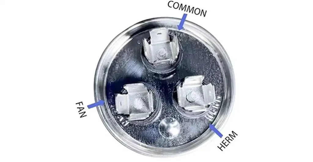
A standard dual run capacitor features three distinct terminals, each serving a specific role in the circuit:
- C (Common): This is the shared terminal. It receives the incoming power from the contactor and distributes it to the other two sections of the capacitor.
- Fan: This terminal connects to the outdoor fan motor. It provides the necessary phase shift to keep the fan blades spinning efficiently.
- Herm: This stands for Hermetic. It is the terminal specifically dedicated to the hermetic compressor—the “heart” of the cooling system.
Why “Hermetic”?
The term “Hermetic” refers to the way the compressor is built. In modern refrigeration tech, the compressor and the motor are sealed together in a welded steel housing. This “hermetic seal” prevents refrigerant leaks and protects the internal components from environmental contaminants. Because this terminal is wired directly to the start winding of that sealed compressor motor, engineers simply labeled it “Herm.”
The Physics of the Start and Run Process
Capacitors function as temporary energy storage devices. In an AC system, the “Herm” terminal provides a constant electrical “push” (measured in microfarads) that creates a secondary phase in the motor’s windings. This phase shift is what allows the compressor to maintain the torque necessary to compress refrigerant gases under high pressure.
The Role of the Hermetic Compressor in Modern Cooling Tech
The hermetic compressor is a cornerstone of modern thermal management technology. Whether it is cooling a residential home or a massive server room housing AI processing units, the efficiency of the compressor depends heavily on the health of the capacitor connected to the “Herm” terminal.
Permanent Split Capacitor (PSC) Motors
Most residential compressors use Permanent Split Capacitor (PSC) technology. These motors require a run capacitor to be energized at all times while the motor is running. The “Herm” terminal ensures that the compressor motor operates with high efficiency and a better power factor. Without the steady phase shift provided by the “Herm” side of the capacitor, the compressor would overheat, draw excessive amperage, and eventually suffer a mechanical failure.
Start Torque and Electrical Load
Starting a compressor is the most taxing moment for any electrical system. The compressor must overcome the “head pressure” of the refrigerant to begin its cycle. The energy stored in the “Herm” circuit provides the initial electrical boost required to transition the motor from a standstill to thousands of RPMs in a fraction of a second. In tech-heavy environments, such as data centers, the reliability of these start/run cycles is the difference between uptime and a catastrophic hardware overheat.
Technical Specifications: Microfarads, Voltage, and Tolerance
When examining a capacitor, the labels provide vital data that dictates how the “Herm” terminal will perform. Understanding these metrics is crucial for anyone performing a hardware review or replacement.
Understanding Microfarads (µF)
The capacity of the “Herm” circuit is measured in microfarads, often symbolized as µF or MFD. A typical dual capacitor might be labeled “45/5 µF.” This means the “Herm” side provides 45 microfarads of capacitance to the compressor, while the “Fan” side provides 5 microfarads to the fan motor.
It is a strict rule in electrical tech that you must match the µF rating exactly. If a compressor requires 45µF and you provide only 35µF via the “Herm” terminal, the motor will run “behind” its phase, causing it to hum, vibrate, and eventually burn out its internal insulation.
Voltage Ratings: 370V vs. 440V
Capacitors also carry a voltage rating, typically 370V or 440V. This is not the amount of electricity the capacitor uses, but rather the maximum amount of “back EMF” (Electromotive Force) it can safely withstand from the motor.
- Tech Tip: You can always use a higher-rated voltage capacitor (e.g., using a 440V capacitor on a 370V system), as it is built to handle more stress. However, you should never go lower, as the capacitor will likely leak or explode under the electrical pressure.
The Significance of Tolerance
Most high-quality capacitors have a tolerance of +/- 5% or 6%. As the internal chemical dielectric of the capacitor degrades over time—often due to heat—the capacitance value of the “Herm” terminal will drop. Once it falls outside of that 5% tolerance, the technology is considered “failed,” even if the compressor is still technically spinning.
Troubleshooting and Hardware Diagnostics
In the digital age, we often think of “troubleshooting” as a software process. However, hardware diagnostics are just as systematic. When a cooling system fails to engage, the “Herm” circuit is the first place a technician looks.
Physical Signs of Failure
Capacitors are designed with a “pressure relief” mechanism. If the internal pressure builds up due to an electrical short or extreme heat, the top of the canister will bulge or “mushroom.” If the “Herm” terminal is sitting on a convex surface rather than a flat one, the component has failed and must be replaced immediately to protect the compressor.
Using a Digital Multimeter for Tech Testing
To accurately test the “Herm” terminal, one must use a digital multimeter with a capacitance (MFD) setting.
- Safety First: The power must be disconnected, and the capacitor must be discharged using a resistor or an insulated screwdriver to prevent a high-voltage shock.
- Testing the Circuit: Place one probe on the “C” (Common) terminal and the other on the “Herm” terminal.
- Reading the Data: If the meter reads “OL” (Open Line) or a value significantly lower than the rated µF on the label, the “Herm” side of the capacitor is dead.
The Impact of “Herm” Failure on System Health
When the “Herm” terminal fails, the compressor may attempt to start but will fail, resulting in a distinct “buzzing” sound followed by a “click” (the thermal overload switch tripping). In the context of tech infrastructure, this failure can lead to rapid temperature spikes. For this reason, many high-end server cooling systems utilize redundant capacitors or “soft start” kits to mitigate the stress on the “Herm” circuit.
The Evolution of Capacitor Technology and Future Trends
As we look toward the future of hardware and energy efficiency, the traditional oil-filled run capacitor is undergoing a transformation. The technology is shifting to meet the demands of a more “green” and digitally controlled world.
Solid-State Alternatives and Inverter Tech
The most significant trend in modern cooling tech is the shift from PSC motors to Inverter-driven motors. Inverter technology converts AC power to DC and then back to a simulated AC at varying frequencies. In these systems, the traditional dual run capacitor with its “Herm” terminal is often replaced by complex circuit boards and power modules. This allows for variable speeds, drastically reducing energy consumption compared to the “all-or-nothing” approach of a standard hermetic compressor.
Improved Dielectric Materials
For systems that still rely on capacitors, material science is providing better dielectrics. Modern capacitors use sophisticated polypropylene films and high-grade synthetic oils to increase the lifespan of the “Herm” circuit. These advancements are critical as global temperatures rise, placing more strain on cooling hardware than ever before.
Conclusion: Why the “Herm” Terminal Matters
While it may seem like a minor detail on a piece of hardware, the “Herm” terminal represents the vital link between electrical supply and mechanical cooling. It is a testament to mid-20th-century engineering that remains relevant in the 21st century. Whether you are a DIY enthusiast, a professional technician, or a tech-stack architect concerned about server room climate control, understanding the role of the hermetic circuit ensures better maintenance, smarter hardware choices, and a longer lifespan for the machines that keep our world cool.
aViewFromTheCave is a participant in the Amazon Services LLC Associates Program, an affiliate advertising program designed to provide a means for sites to earn advertising fees by advertising and linking to Amazon.com. Amazon, the Amazon logo, AmazonSupply, and the AmazonSupply logo are trademarks of Amazon.com, Inc. or its affiliates. As an Amazon Associate we earn affiliate commissions from qualifying purchases.