
The question “what color is a hot wire?” might seem deceptively simple, a query one might expect from a DIY enthusiast attempting a quick home repair. However, for professionals operating within the technology sector, understanding the color-coding of electrical wiring, particularly “hot” wires, is far more than a matter of casual curiosity. It’s a fundamental aspect of electrical safety, system design, diagnostic troubleshooting, and compliance with industry standards. In the realm of technology, where circuits are increasingly complex and miniaturized, and where power delivery is critical for everything from data centers to edge computing devices, a nuanced understanding of wire color conventions is paramount. This article delves into the significance of hot wire colors, exploring their implications for electrical engineers, technicians, system administrators, and anyone involved in the design, installation, maintenance, or repair of technological systems.

The Universal Language of Electrical Color Codes
Electrical wiring color codes are not arbitrary; they are a codified system designed to enhance safety and prevent misidentification of conductors. This standardization is crucial, especially when dealing with alternating current (AC) and direct current (DC) systems, each with its own set of conventions. While regional variations exist, a common understanding forms the bedrock of safe electrical practices globally.
Navigating AC Power Systems and Hot Wire Identification
In AC power systems, the “hot” wire, also known as the “live” or “phase” wire, carries the electrical potential that drives current flow. Identifying this wire accurately is essential to prevent accidental contact and potential electrocution. The color coding for AC hot wires can vary significantly depending on the geographical location and the voltage class of the system.
North American Conventions: A Closer Look
In North America (primarily the United States and Canada), the National Electrical Code (NEC) provides guidelines for wire color coding. For standard 120V and 240V systems:
-
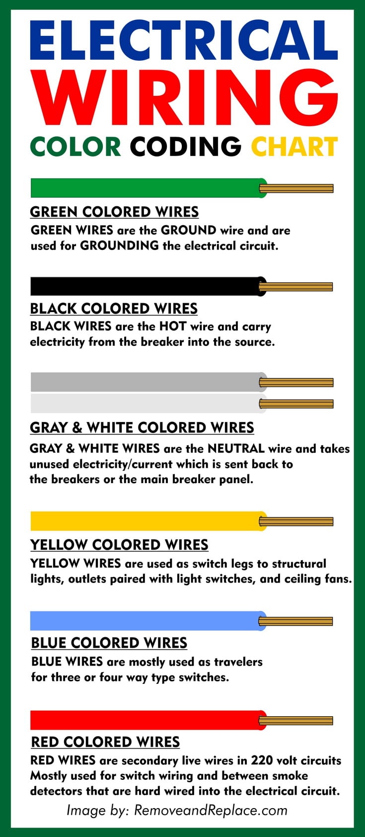
Hot Wires: Typically, hot wires are identified by black, red, and blue insulation. In a single-phase circuit, a single hot wire is usually black. In a 240V circuit (which utilizes two hot wires and a neutral), both hot wires might be black, or one might be black and the other red. For more complex multi-phase systems, red and blue are often used for subsequent phases. It’s crucial to note that older installations might not adhere strictly to these modern conventions, underscoring the importance of careful verification.
-
Neutral Wire: The neutral wire, which completes the circuit by providing a return path for current, is conventionally colored white or gray.
-
Ground Wire: The safety ground wire, designed to carry fault current safely to the earth, is typically green, green with a yellow stripe, or bare copper.
The NEC allows for some flexibility, stating that any color other than green, green with a yellow stripe, white, or gray can be used for a hot wire if it is permanently identified at termination points by appropriate marking (e.g., tape or labels). This flexibility, while practical in some scenarios, emphasizes the need for meticulous documentation and labeling in any technological installation.
International Variations: A Global Perspective
Beyond North America, other regions employ different color codes, which can create challenges for international tech deployments and collaborations.
- European Standards (IEC): In countries adhering to the International Electrotechnical Commission (IEC) standards, the common colors for AC wiring are:
- Phase (Hot) Wires: Typically brown, black, and gray. In a single-phase system, brown is usually the primary hot wire. For three-phase systems, the sequence is brown, black, and gray.
- Neutral Wire: Conventionally blue.
- Protective Earth (Ground) Wire: Green with a yellow stripe.
The IEC’s color coding system offers a clear distinction between phase, neutral, and ground, which can simplify wiring in many contexts. However, the presence of three different colors for hot wires in a three-phase system requires careful attention to phase sequencing, especially in applications involving motor control or synchronized power distribution.
- Other Regional Codes: It’s important to be aware that other countries may have their own specific wiring color codes. For instance, in some older Australian installations, red and black were used for live and neutral respectively, with blue for switched live. This highlights the necessity for tech professionals to consult local electrical codes and standards whenever working in a new or unfamiliar region.
DC Systems: A Different Palette
Direct current (DC) systems, commonly found in electronic devices, battery systems, and many renewable energy installations, generally employ a simpler color-coding scheme.
- Positive (+) Terminal/Wire: Conventionally, the positive DC wire is represented by red. This color is widely recognized for positive voltage.

-
Negative (-) Terminal/Wire: The negative DC wire is typically colored black.
-
Ground/Return: In some DC systems, a ground or return path might be indicated by white or green, depending on the specific application and its grounding strategy. For instance, in automotive electrical systems, red is positive and black is negative. In some lower-voltage electronic circuits, a white wire might serve as the negative return.
The consistency in DC color coding, with red for positive and black for negative, simplifies identification and reduces the risk of polarity reversal, which can be catastrophic for sensitive electronic components.
The Critical Role of Color Coding in Technology
For professionals in the tech industry, understanding and adhering to wire color codes is not just about preventing shocks; it’s integral to the efficient and safe operation of complex technological systems.
Safety First: Preventing Electrocution and Equipment Damage
The most immediate and critical implication of correctly identifying hot wires lies in electrical safety. Accidental contact with a hot wire can result in severe burns, electrocution, and potentially fatal outcomes. In technological environments, where high voltages can be present in power supplies, servers, and industrial control systems, the risk is amplified. Proper color coding acts as an immediate visual warning, allowing technicians to distinguish between live conductors and neutral or ground wires, thereby minimizing the chance of dangerous mistakes during installation, maintenance, or repair.
Furthermore, incorrect wiring can lead to significant equipment damage. Connecting a hot wire to a neutral or ground terminal, or reversing polarity in a DC system, can instantly destroy sensitive electronic components, leading to costly downtime and replacement expenses. In data centers, where uninterrupted power is paramount, such errors can have cascading effects, impacting critical business operations.
Troubleshooting and Diagnostics: The Efficiency Advantage
When a technological system malfunctions, troubleshooting becomes a critical phase. The ability to quickly and accurately identify the status of electrical connections is essential for efficient problem-solving. Technicians can use wire colors as a primary indicator during diagnostic processes. For example, if a particular circuit is not receiving power, a technician can visually inspect the wiring, looking for the expected hot wire color, and verify its connection and continuity. This speeds up the identification of faults, whether they lie in the power source, the wiring itself, or the connected components.
In complex networked systems or industrial automation, where numerous wires converge, color coding provides an organized framework for tracing circuits and understanding power flow. Without standardized colors, troubleshooting would devolve into a laborious and error-prone process of tracing individual wires by continuity testing alone.
System Design and Installation: Building for Reliability
During the design and installation phases of technological systems, adherence to color coding standards is fundamental for building reliable and maintainable infrastructure. Engineers specify wiring colors in schematics and blueprints, ensuring that installers have a clear guide. This standardized approach facilitates:
- Interoperability: When integrating equipment from different manufacturers or deploying systems in diverse geographical locations, common wire color conventions ensure that components can be safely and correctly connected.
- Maintainability: Future maintenance or upgrades are significantly simplified when wiring is color-coded according to established standards. Technicians can readily understand the existing electrical layout, reducing the time and effort required for modifications.
- Compliance: Many industries and regulatory bodies mandate adherence to specific electrical wiring standards. Non-compliance can lead to failed inspections, project delays, and legal liabilities.
The Importance of Beyond-Color Verification
While color coding is an invaluable tool, it is crucial to emphasize that it should never be the sole basis for identifying a hot wire, especially in professional tech environments. Several factors necessitate a more robust approach:
- Aging Installations: Older electrical systems may not conform to current color coding standards due to outdated practices or renovations.
- Non-Standard Practices: While less common in professionally installed systems, DIY modifications or poorly documented work can introduce non-standard wiring colors.
- Damaged Insulation: Over time, wire insulation can degrade, crack, or be damaged, potentially obscuring the original color.
- Intentional Modifications: In specialized applications, engineers might intentionally deviate from standard colors for specific system logic, but this should always be accompanied by clear labeling and documentation.
Therefore, professionals must always employ verification tools to confirm the presence of voltage. A non-contact voltage tester, a multimeter, or a circuit tester should be used to definitively identify live conductors before any work is performed. These tools provide an objective measurement of electrical potential, overriding any assumptions based solely on wire color.
Conclusion: A Foundation of Safety and Efficiency in Technology
The question “what color is a hot wire?” may have simple answers in isolation, but its implications within the technology sector are profound. From the fundamental principle of electrical safety to the nuanced requirements of complex system design and troubleshooting, wire color coding serves as a universal language that underpins reliable and secure technological operations.
For tech professionals, a thorough understanding of AC and DC color conventions, including regional variations, is not merely a matter of compliance but a cornerstone of their expertise. It enables them to prevent accidents, safeguard valuable equipment, diagnose problems efficiently, and build systems that are robust and maintainable. While color coding provides an indispensable visual guide, it must always be complemented by the diligent use of verification tools. By embracing this dual approach – understanding the language of colors and verifying with precision – technology professionals can ensure that the power that drives innovation flows safely and reliably.
aViewFromTheCave is a participant in the Amazon Services LLC Associates Program, an affiliate advertising program designed to provide a means for sites to earn advertising fees by advertising and linking to Amazon.com. Amazon, the Amazon logo, AmazonSupply, and the AmazonSupply logo are trademarks of Amazon.com, Inc. or its affiliates. As an Amazon Associate we earn affiliate commissions from qualifying purchases.