In the rapidly evolving landscape of additive manufacturing, the complexity of a 3D-printed object is often hidden beneath its surface. While the external “shell” provides the aesthetic and dimensional accuracy of a part, the internal structure—known as infill—dictates the part’s weight, strength, material consumption, and print time.
For engineers, hobbyists, and industrial designers, mastering infill is a fundamental step in transitioning from basic printing to advanced manufacturing. Understanding what infill is, how it functions, and how to optimize it using modern slicing software is essential for creating parts that are not only functional but also efficient. This guide explores the technical nuances of infill and provides a roadmap for selecting the perfect internal geometry for any project.
1. Understanding the Fundamentals of Infill
At its core, infill is the repetitive pattern that occupies the space inside a 3D-printed object. Unlike traditional manufacturing methods like injection molding, which typically produce solid parts, 3D printing allows for “semi-hollow” interiors. This capability is one of the primary advantages of 3D printing technology, offering a level of control over internal physics that was previously impossible.
The Definition and Purpose of Infill
Infill serves as the internal support system for a 3D print. If you were to print a solid cube without infill, the top layers would have no foundation to rest upon and would collapse into the hollow center—a phenomenon known as “pillowing.” Infill provides a scaffold for these top layers while simultaneously giving the object its structural integrity.
Beyond support, infill serves three critical functions:
- Structural Strength: It determines how much mechanical stress a part can endure.
- Material Efficiency: By using a hollow pattern instead of a solid mass, users can save significant amounts of filament or resin.
- Time Management: Printing a solid object takes exponentially longer than printing one with a sparse internal pattern.
The Balance Between Strength, Material, and Time
The “Golden Triangle” of 3D printing involves balancing strength, material usage, and print speed. If you increase the amount of infill, the part becomes stronger and heavier, but it also consumes more plastic and takes much longer to print. Conversely, reducing infill saves time and money but may result in a fragile part. In a professional tech environment, optimizing this balance is the difference between a cost-effective prototype and an expensive failure.
2. Key Infill Parameters: Density and Pattern
When configuring a 3D print in a “slicer” (the software that converts a 3D model into G-code), the two most important settings regarding the interior are Infill Density and Infill Pattern.
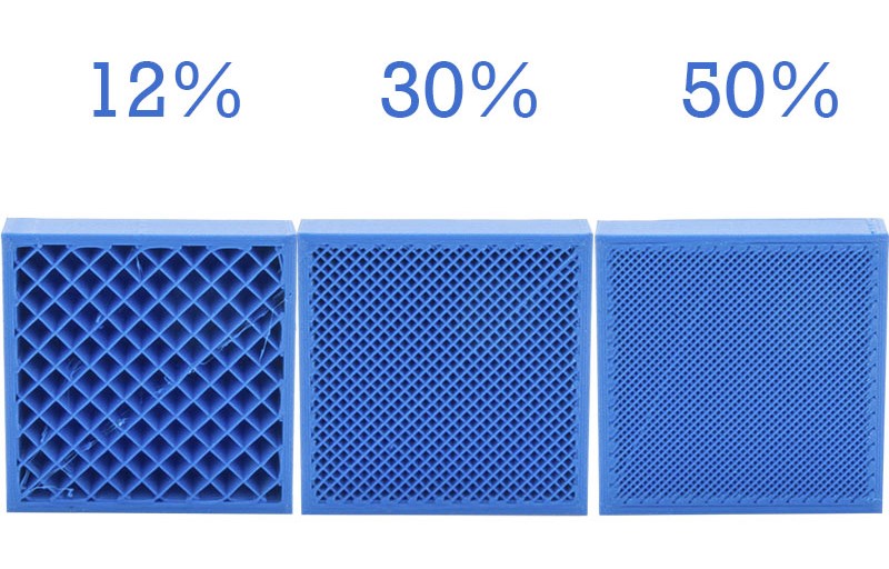
Infill Density Explained
Infill density is measured as a percentage, ranging from 0% (completely hollow) to 100% (completely solid).
- 0%–15%: Ideal for decorative models, display pieces, or rapid visual prototypes where mechanical strength is not a requirement.
- 15%–50%: The “standard” range for most functional parts. This provides a robust balance of durability and efficiency.
- 50%–100%: Reserved for high-stress components, tools, or parts that require significant weight. Interestingly, moving from 70% to 100% density often yields diminishing returns in strength while drastically increasing print time and the risk of internal warping.
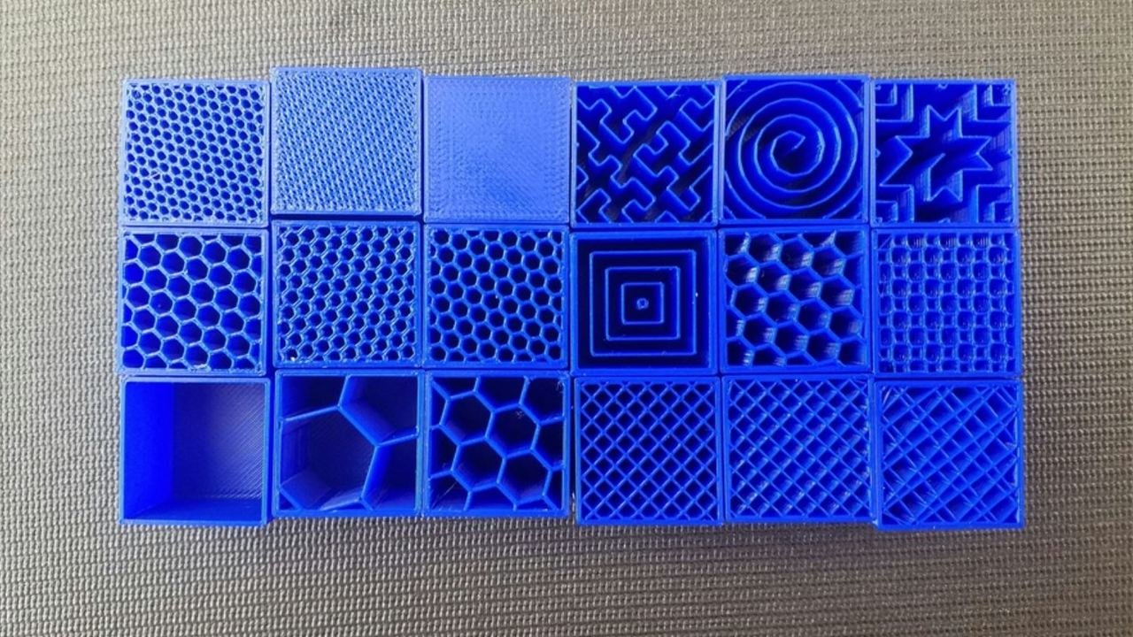
Popular Infill Patterns and Their Mechanical Properties
Modern slicing software offers a variety of geometric patterns, each with unique advantages:
- Grid and Lines: These are the most common patterns. They are fast to print but are primarily strong in two dimensions. They can occasionally cause nozzle interference because the lines overlap on the same layer.
- Honeycomb: Known for its high strength-to-weight ratio. While visually appealing and structurally sound, it is time-consuming to print because the print head must frequently change direction.
- Gyroid: The current favorite among tech enthusiasts. The gyroid is a “triply periodic minimal surface” that provides equal strength in all directions (isotropic). It allows for high print speeds and promotes airflow, making it excellent for parts exposed to heat.
- Cubic: A 3D pattern that consists of stacked cubes tilted on their corners. This provides excellent compressive strength and ensures the part is equally strong regardless of which way it is pulled or pushed.
3. How to Choose the Right Infill for Your Project
Selecting the right infill is not a “one size fits all” decision. It requires a technical assessment of the part’s intended use-case and the environmental stressors it will face.
Functional Prototypes vs. Aesthetic Models
If you are printing a figurine for a desk, a 10% “Lightning” or “Lines” infill is sufficient. These patterns prioritize speed and top-layer support over internal rigidity. However, if you are printing a mounting bracket for a piece of tech hardware, you need a pattern like “Cubic” or “Gyroid” at a density of at least 30%. In these cases, the internal structure must resist shearing forces and vibrations.
Specialized Applications: Flexible and Load-Bearing Parts
When printing with flexible filaments like TPU (Thermoplastic Polyurethane), the infill pattern dictates the “squishiness” of the part. A “Cross” or “Gyroid” pattern allows the object to compress and rebound uniformly.
For load-bearing parts, such as gears or levers, users should focus more on the number of “walls” (perimeters) rather than just infill density. Technical testing has shown that increasing the wall thickness often adds more strength per gram of filament than simply increasing the infill density. A common professional strategy is to use 4-6 walls with a 25% gyroid infill for a part that is virtually indestructible under normal conditions.
4. Advanced Infill Optimization and Software Settings
As 3D printing software becomes more sophisticated, users can now manipulate infill in ways that mimic high-end engineering simulations.
Graduated Infill and Modifiers
One of the most powerful trends in 3D printing tech is “Graduated Infill.” Instead of having a uniform 20% density throughout the entire part, advanced slicers allow for variable density. You can program the software to use 10% density in the base of a model and 40% density near the top where the part connects to a mechanical joint. This “smart” distribution of material saves resources while placing strength exactly where the physics of the part demands it.
The Role of “Infill Walls” and Overlap
To ensure the infill actually strengthens the part, it must be properly bonded to the outer shells. The “Infill Overlap” setting controls how far the infill lines extrude into the wall perimeters. A higher overlap percentage ensures that the internal skeleton and the external skin are fused into a single monolithic structure, preventing delamination under stress.
Support Infill
Infill is not only used inside the final part but also in the “support structures” that hold up overhanging geometry during the print process. Choosing a low-density “Zig-Zag” or “Cross” pattern for supports ensures they are sturdy enough to hold the weight of the molten plastic but brittle enough to be easily broken away once the print is finished.
5. The Future of Infill: AI and Generative Design
The next frontier for infill technology lies in Artificial Intelligence and Generative Design. We are moving away from simple geometric repetitions toward biologically inspired structures.
Algorithmic Internal Structures
Tech companies are now developing AI-driven slicing algorithms that perform real-time Stress Analysis (Finite Element Analysis) on a 3D model. Instead of filling a part with a standard grid, the software generates a complex, non-repeating lattice that mimics the internal structure of bird bones—extremely light but reinforced along specific “load paths.”
Biomimicry and Lattice Engineering
Lattice structures are the high-tech evolution of infill. By using mathematical formulas to create porous, bone-like interiors, manufacturers in the aerospace and medical sectors are creating implants and engine components that are 70% lighter than solid counterparts without sacrificing safety. As these tools trickle down to consumer-grade software, the definition of “infill” will shift from a simple toggle switch to a sophisticated exercise in structural engineering.

Conclusion
Infill is far more than just a way to fill the empty space inside a 3D print. It is the architectural backbone of additive manufacturing. By understanding the interplay between density and pattern, and by leveraging advanced software features like graduated infill and gyroid geometries, users can produce parts that are optimized for both performance and cost.
As 3D printing continues to integrate with AI and generative design, the ability to manipulate the “hidden” interior of objects will remain one of the most powerful tools in the modern designer’s arsenal. Whether you are building a simple gadget or a complex mechanical assembly, the secret to success lies not just in what the world sees on the outside, but in the strategic engineering of the infill within.
aViewFromTheCave is a participant in the Amazon Services LLC Associates Program, an affiliate advertising program designed to provide a means for sites to earn advertising fees by advertising and linking to Amazon.com. Amazon, the Amazon logo, AmazonSupply, and the AmazonSupply logo are trademarks of Amazon.com, Inc. or its affiliates. As an Amazon Associate we earn affiliate commissions from qualifying purchases.