
In the intricate world of engineering and technology, where precision, reliability, and innovation are paramount, understanding fundamental concepts is crucial. One such concept, often encountered in the design and analysis of mechanical components, is the “polar moment of inertia.” Far from being an arcane academic term, it is a vital metric that underpins the structural integrity and performance of countless technological devices and systems, from the smallest drone propeller to the largest wind turbine shaft.
At its core, the polar moment of inertia quantifies a component’s resistance to twisting or torsional deformation. Imagine trying to twist a wrench or turn a screwdriver; the effort required depends not only on the material but also significantly on the shape and size of the cross-section you are twisting. This geometrical property, inherent to the cross-section of an object, directly influences how well a component can withstand torsional forces without yielding or failing. In an era where digital tools, advanced materials, and intricate designs dominate product development, a deep understanding of the polar moment of inertia is essential for engineers aiming to create safe, efficient, and robust technological solutions. This article delves into what the polar moment of inertia is, why it matters profoundly in modern tech, and how it’s applied in today’s digital engineering workflows.
The Foundation of Torsional Resistance in Engineering Design
The polar moment of inertia is a cornerstone concept in solid mechanics, particularly within the study of torsion. It’s a geometrical property that describes how a cross-section’s area is distributed around its centroid, specifically in relation to resisting twisting forces.
Understanding Torsion and Stress Distribution
Torsion refers to the twisting of an object due to an applied torque. When a torsional force acts on a component, such as a shaft, it induces shear stresses within the material. These shear stresses are not uniformly distributed across the cross-section; they are typically zero at the centroid (the axis of twist) and reach their maximum value at the outermost fibers. The ability of a component to resist this twisting and the resulting shear stresses without excessive deformation or failure is directly linked to its cross-sectional geometry and, specifically, its polar moment of inertia. Engineers must carefully consider these stresses to prevent catastrophic failures, especially in applications where rotating components are subjected to dynamic loads, like in automotive drive shafts, aircraft engine components, or robotic joints. Without adequate torsional resistance, these components could deform plastically, leading to functional impairment, or fracture entirely, posing significant safety risks.
Defining Polar Moment of Inertia (J or Ip)
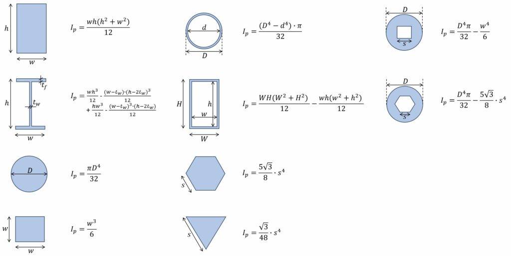
The polar moment of inertia, commonly denoted as $J$ or $I_p$, is a measure of a cross-section’s resistance to torsional deformation. Mathematically, it’s defined as the second moment of area with respect to an axis perpendicular to the plane of the cross-section and passing through its centroid. For a general cross-section, it’s calculated by integrating the square of the distance from each infinitesimal area element to the centroidal axis.
For common shapes, the formulas are simpler:
- For a solid circular cross-section: $J = frac{pi d^4}{32}$, where $d$ is the diameter.
- For a hollow circular cross-section: $J = frac{pi (D^4 – d^4)}{32}$, where $D$ is the outer diameter and $d$ is the inner diameter.
The units for polar moment of inertia are typically length to the fourth power (e.g., $mm^4$ or $in^4$). It’s crucial to remember that $J$ is a geometrical property of the cross-section, independent of the material from which the component is made. The material’s resistance to shear (quantified by its shear modulus) works in conjunction with the polar moment of inertia to determine the overall torsional stiffness and strength of the component. A larger polar moment of inertia indicates greater resistance to twisting for a given torque, making it a critical parameter in the design phase.
Distinguishing from Area Moment of Inertia
It’s common for engineers and students to confuse the polar moment of inertia ($J$ or $Ip$) with the area moment of inertia ($Ix$ or $I_y$), also known as the second moment of area or moment of inertia of area. While both are geometrical properties of a cross-section, they relate to different types of deformation:
- Area Moment of Inertia ($Ix$, $Iy$): This describes a cross-section’s resistance to bending about a specific axis (x or y). It’s used to calculate bending stresses and deflections when a component is subjected to forces perpendicular to its longitudinal axis.
- Polar Moment of Inertia ($J$ or $I_p$): This describes a cross-section’s resistance to twisting or torsion about an axis perpendicular to the cross-section. It’s used to calculate shear stresses and angular deflections under torsional loads.
The relationship between them is straightforward for planar cross-sections: $J = Ix + Iy$, where $Ix$ and $Iy$ are the area moments of inertia about any two perpendicular axes passing through the centroid of the cross-section. Understanding this distinction is fundamental for correctly analyzing and designing components subjected to various loading conditions in technological applications.
Why Polar Moment of Inertia Matters in Modern Tech and Engineering
In the rapidly evolving landscape of technology, where performance, durability, and miniaturization are key drivers, the polar moment of inertia plays an indispensable role. Its accurate consideration is not just good practice; it’s a prerequisite for innovation and success.
Critical Role in Component Design and Analysis
Every rotating component in mechanical systems, from the microscopic gears in a smartwatch to the massive shafts in industrial machinery, is subjected to torsional forces. The polar moment of inertia is a fundamental parameter in their design. For example, in the automotive industry, drive shafts transmit power from the engine to the wheels; their ability to withstand the engine’s torque depends on their polar moment of inertia. Similarly, in robotics, the joints and arms of robotic manipulators must be designed with sufficient torsional stiffness to ensure precise movement and prevent unwanted deflection under load. Aerospace engineers rely on $J$ to design propeller shafts, turbine components, and structural elements that endure extreme torsional stresses during flight. Without properly sizing components based on their polar moment of inertia, the risk of fatigue failure, excessive vibration, and compromised performance increases dramatically across all these tech sectors.
Enhancing Product Reliability and Safety
The failure of a single component due to insufficient torsional resistance can have cascading effects, leading to system failure, costly repairs, and even catastrophic accidents. Consider medical devices, where precision and reliability are non-negotiable, or infrastructure components like those in wind turbines, which operate under constant, varying loads for decades. By accurately calculating and designing for the appropriate polar moment of inertia, engineers can ensure that components not only meet their performance specifications but also possess the necessary resilience to withstand expected and unexpected torsional stresses throughout their operational lifespan. This proactive approach to design directly translates into enhanced product reliability, extended service life, and, critically, improved safety for users and operators, which is a paramount concern in all technological deployments.
Optimizing Material Usage and Weight Reduction
In many advanced tech fields, particularly aerospace, drones, and portable electronics, weight reduction is a critical design objective. Less weight often translates to improved fuel efficiency, greater payload capacity, longer battery life, and enhanced maneuverability. However, reducing weight cannot come at the expense of structural integrity. This is where the understanding of polar moment of inertia becomes invaluable. Engineers can use $J$ to optimize cross-sectional geometries, identifying shapes that provide maximum torsional resistance with the minimum amount of material. For instance, a hollow shaft generally offers a higher polar moment of inertia per unit of weight compared to a solid shaft of the same outer diameter, making it an efficient choice for transmitting torque where weight is a constraint. This optimization, guided by the principles of polar moment of inertia, allows for “lightweighting” without compromising strength, pushing the boundaries of what is possible in high-performance technological applications.
Calculating and Applying Polar Moment of Inertia in Digital Engineering Workflows
The complexity of modern engineering designs often precludes simple hand calculations. Digital tools have become indispensable in accurately determining and applying the polar moment of inertia.
Manual Calculations vs. Computational Tools
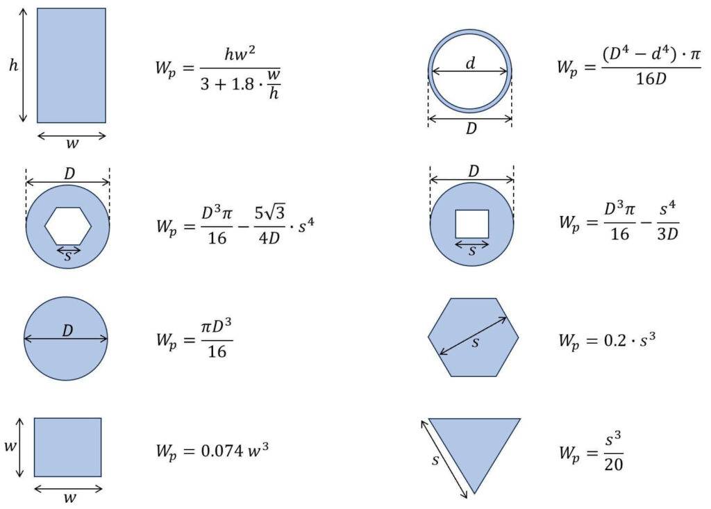
For basic geometries like solid or hollow circular shafts, the polar moment of inertia can be calculated relatively easily using the formulas mentioned earlier. These manual calculations are fundamental for understanding the concept and for preliminary design assessments. However, real-world components rarely possess such idealized cross-sections. Many tech products feature complex, irregular, or asymmetric shapes designed to meet multiple performance criteria. For these intricate geometries, manual calculation of $J$ becomes incredibly tedious, prone to error, and often impractical.
This is where computational tools come into play. Modern Computer-Aided Design (CAD) software packages (e.g., SolidWorks, Autodesk Inventor, CATIA) are equipped with built-in functionalities to automatically calculate the geometrical properties of any drawn cross-section, including its polar moment of inertia, with high precision. This capability frees engineers from laborious manual calculations, allowing them to focus on the creative and analytical aspects of design.
Leveraging Simulation and FEA Software
Beyond mere calculation, the true power of understanding and applying the polar moment of inertia is realized through Computer-Aided Engineering (CAE) tools, particularly Finite Element Analysis (FEA) software. Programs like ANSYS, Abaqus, COMSOL Multiphysics, and SolidWorks Simulation allow engineers to simulate how a component will behave under various loading conditions, including torsional stresses.
FEA software works by dividing a complex geometry into a mesh of smaller, simpler elements. It then applies mathematical equations to these elements to determine stress, strain, and deformation throughout the entire component. When a torsional load is applied in an FEA simulation, the software implicitly uses the principles behind the polar moment of inertia to calculate the resulting shear stresses and angular deflection. Engineers can visualize stress distribution maps, identify areas of high stress concentration, and predict where failure might occur. This capability is invaluable for validating designs before physical prototyping, saving significant time and resources in the product development cycle.
Iterative Design and Optimization in a Digital Environment
The seamless integration of CAD and CAE tools facilitates an iterative design and optimization process that is critical in today’s fast-paced tech industry. Engineers can quickly modify a component’s cross-section in CAD, instantly recalculate its polar moment of inertia, and then run an FEA simulation to assess the impact of the changes on its torsional performance.
This rapid feedback loop allows for extensive exploration of design alternatives. For instance, an engineer might experiment with different wall thicknesses for a hollow shaft, various ribbing patterns, or even non-circular cross-sections, all while ensuring that the component maintains adequate torsional strength and stiffness. This digital iteration process enables engineers to optimize designs not only for performance (e.g., minimizing deflection under torque) but also for manufacturing constraints, material cost, and weight targets, ultimately leading to superior, more efficient, and more marketable technological products.
Real-World Tech Applications and Future Trends
The polar moment of inertia isn’t confined to textbooks; its principles are actively applied across a spectrum of cutting-edge technological fields, constantly evolving with new materials and design methodologies.
Robotics and Automation
In the field of robotics, the precision and agility of robotic arms are paramount. Each joint, link, and end-effector experiences torsional loads during movement and manipulation tasks. A robotic arm needs to be stiff enough to avoid excessive deflection, which could compromise accuracy, while also being lightweight to maximize speed and payload capacity. Engineers designing robotic systems meticulously analyze the polar moment of inertia of each segment to ensure optimal torsional rigidity. This is especially critical for collaborative robots (cobots) where safety and predictable motion are vital, and for high-speed industrial robots where dynamic stability under torque is essential for productivity and repetitive tasks.
Aerospace and Automotive Engineering
These industries are arguably among the most demanding when it comes to structural integrity and performance-to-weight ratios. In aerospace, components like propeller shafts, turbine engine shafts, and control surface actuators are under constant torsional stress. Their design, heavily reliant on a precise understanding of $J$, ensures they can operate reliably in extreme conditions. In automotive engineering, drive shafts, axles, and steering columns must transmit significant torque efficiently and safely. The design of vehicle chassis and suspension components also considers torsional stiffness to enhance handling and ride comfort. Future advancements in electric vehicles (EVs) and autonomous driving further emphasize the need for robust and optimized components, where the polar moment of inertia will continue to be a key design parameter.
Emerging Fields: Additive Manufacturing and Advanced Materials
The rise of additive manufacturing (3D printing) and the development of advanced materials (e.g., composites, metamaterials) are introducing new complexities and opportunities for applying the polar moment of inertia. When designing components for 3D printing, especially with anisotropic materials (materials whose properties vary with direction), traditional assumptions about material behavior under torsion may no longer hold. Engineers must use advanced computational models and simulations to understand how the printed component’s unique microstructure affects its effective polar moment of inertia and overall torsional resistance. This necessitates a deeper, often simulation-driven, analysis of $J$ to fully exploit the design freedom offered by additive manufacturing while ensuring structural integrity.
The Role of AI and Generative Design
Looking ahead, artificial intelligence (AI) and generative design are poised to revolutionize how engineers approach concepts like the polar moment of inertia. Generative design algorithms, fed with performance requirements (including desired torsional stiffness derived from $J$), material properties, and manufacturing constraints, can autonomously explore thousands of design permutations. AI can then suggest optimized geometries that achieve specific torsional resistance with minimal material, often leading to unconventional yet highly efficient shapes that human designers might not conceive. This AI-driven approach will significantly accelerate the iterative design process, allowing for the rapid development of components that are perfectly tuned for their torsional requirements, further blurring the lines between structural analysis and intelligent design in the tech sphere.
Conclusion
The polar moment of inertia, while a seemingly abstract engineering concept, is a powerful and indispensable tool at the heart of modern technological advancement. It serves as a fundamental metric for quantifying a component’s resistance to twisting, dictating its structural integrity, reliability, and safety in countless applications. From ensuring the precise movements of a robotic arm to guaranteeing the safe transmission of power in an aircraft engine, its influence is pervasive.
In an era defined by digital engineering, the role of polar moment of inertia has evolved from a manual calculation to an integral part of sophisticated CAD, CAE, and FEA workflows. These tools empower engineers to simulate, optimize, and iterate designs with unprecedented speed and accuracy, facilitating the creation of lighter, stronger, and more efficient tech products. As we venture into new frontiers like additive manufacturing, advanced materials, and AI-driven generative design, the principles encapsulated by the polar moment of inertia will continue to be a cornerstone. Understanding and effectively applying this concept remains paramount for engineers striving to push the boundaries of innovation, ensuring that the technological solutions of today and tomorrow are not only groundbreaking but also inherently robust and reliable.
aViewFromTheCave is a participant in the Amazon Services LLC Associates Program, an affiliate advertising program designed to provide a means for sites to earn advertising fees by advertising and linking to Amazon.com. Amazon, the Amazon logo, AmazonSupply, and the AmazonSupply logo are trademarks of Amazon.com, Inc. or its affiliates. As an Amazon Associate we earn affiliate commissions from qualifying purchases.